® Total Access 1240 Installation and Maintenance Practice Document Number: 61179605L5-5B September 2005
Total Access 1240 Installation and Maintenance Practice Trademarks Front Matter Any brand names and product names included in this manual are trademarks, registered trademarks, or trade names of their respective holders. To the Holder of the Manual The contents of this publication are current as of the date of publication. ADTRAN® reserves the right to change the contents without prior notice.
Revision History Revision Date Description A December 2004 Initial release B September 2005 This revision includes updates to the User Interface and Application Guidelines sections, general updates to the power and ground connection information, and updates to the Ethernet and VLAN interface information. Conventions The following typographical conventions are used in this document: This font indicates a cross-reference link. First-time references to tables and figures are shown in this font.
Total Access 1240 Installation and Maintenance Practice Training ADTRAN offers training courses on our products. These courses include overviews on product features and functions while covering applications of ADTRAN’s product lines. ADTRAN provides a variety of training options, including customized training and courses taught at our facilities or at customer sites. For inquiries concerning training, contact ADTRAN: Training Phone: 800-615-1176, ext.
Contents Section 1 Introduction . . . . . . . . . . . . . . . . . . . . . . . . . . . . . . . . . . . . . . . . . . . . . . . . . . . . . . . . . . . . . . . . . . . . 1-1 General . . . . . . . . . . . . . . . . . . . . . . . . . . . . . . . . . . . . . . . . . . . . . . . . . . . . . . . . . . . . . . . . . . . . . . . . . . . . . Description . . . . . . . . . . . . . . . . . . . . . . . . . . . . . . . . . . . . . . . . . . . . . . . . . . . . . . . . . . . . . . . . . . . . . . . Features . . . . . . . .
Total Access 1240 Installation and Maintenance Practice Section 4 Provisioning Defaults . . . . . . . . . . . . . . . . . . . . . . . . . . . . . . . . . . . . . . . . . . . . . . . . . . . . . . . . . . . . 4-1 Introduction . . . . . . . . . . . . . . . . . . . . . . . . . . . . . . . . . . . . . . . . . . . . . . . . . . . . . . . . . . . . . . . . . . . . . . . . . 4-1 Section 5 User Interface. . . . . . . . . . . . . . . . . . . . . . . . . . . . . . . . . . . . . . . . . . . . . . . . . . . . . . . .
Contents SNMP Contact Information Menu . . . . . . . . . . . . . . . . . . . . . . . . . . . . . . . . . . . . . . . . . . . . . . SNMP Community Names Menu . . . . . . . . . . . . . . . . . . . . . . . . . . . . . . . . . . . . . . . . . . . . . . SNMP Trap Hosts Menu . . . . . . . . . . . . . . . . . . . . . . . . . . . . . . . . . . . . . . . . . . . . . . . . . . . . . External Alarms Menu . . . . . . . . . . . . . . . . . . . . . . . . . . . . . . . . . . . . . . . . . . . . . . . . . . . . . . . . .
Total Access 1240 Installation and Maintenance Practice Appendix B SCA File Format. . . . . . . . . . . . . . . . . . . . . . . . . . . . . . . . . . . . . . . . . . . . . . . . . . . . . . . . . . . . . . . . . B-1 SCA Format . . . . . . . . . . . . . . . . . . . . . . . . . . . . . . . . . . . . . . . . . . . . . . . . . . . . . . . . . . . . . . . . . . . . . . . . . B-1 File Format . . . . . . . . . . . . . . . . . . . . . . . . . . . . . . . . . . . . . . . . . . . . . . . . . . . . . . . . . . . . .
Contents Figures Figure 1-1. Figure 1-2. Figure 1-3. Figure 2-1. Figure 2-2. Figure 2-3. Figure 3-1. Figure 3-2. Figure 3-3. Figure 3-4. Figure 3-5. Figure 3-6. Figure 3-7. Figure 3-8. Figure 3-9. Figure 5-1. Figure 5-2. Figure 5-3. Figure 5-4. Figure 5-5. Figure 5-6. Figure 5-7. Figure 5-8. Figure 5-9. Figure 5-10. Figure 5-11. Figure 5-12. Figure 5-13. Figure 5-14. Figure 5-15. Figure 5-16. Figure 5-17. Figure 5-18. Figure 5-19. Figure 5-20. Figure 5-21. Figure 5-22. Figure 5-23. Figure 5-24.
Total Access 1240 Installation and Maintenance Practice Figure 5-33. Figure 5-34. Figure 5-35. Figure 5-36. Figure 5-37. Figure 5-38. Figure 5-39. Figure 5-40. Figure 5-41. Figure 5-42. Figure 5-43. Figure 5-44. Figure 5-45. Figure 5-46. Figure 5-47. Figure 5-48. Figure 5-49. Figure 5-50. Figure 5-51. Figure 5-52. Figure 5-53. Figure 5-54. Figure 5-55. Figure 5-56. Figure 5-57. Figure 5-58. Figure 5-59. Figure 5-60. Figure 5-61. Figure 5-62. Figure 5-63. Figure 5-64. Figure 5-65. Figure 5-66. Figure 5-67.
Contents Tables Table 1-1. Table 3-1. Table 3-2. Table 3-3. Table 4-1. Table 4-2. Table 4-3. Table 4-4. Table 4-5. Table 5-1. Table 5-2. Table 5-3. Table 5-4. Table 5-5. Table 5-6. Table 5-7. Table 5-8. Table 5-9. Table 5-10. Table 5-11. Table 5-12. Table 5-13. Table 5-14. Table 5-15. Table 5-16. Table 5-17. Table 5-18. Table 5-19. Table 5-20. Table 5-21. Table 5-22. Table 5-23. Table 5-24. Table 5-25. Table 5-26. Table 5-27. Table 5-28. Table 5-29. Table 5-30. Table 5-31. Table 5-32. Table 5-33.
Total Access 1240 Installation and Maintenance Practice Table 5-39. Table 5-40. Table 5-41. Table 5-42. Table 5-43. Table 5-44. Table 5-45. Table 5-46. Table 5-47. Table 5-48. Table 5-49. Table 5-50. Table 5-51. Table 5-52. Table 5-53. Table 5-54. Table 5-55. Table 5-56. Table 5-57. Table 5-58. Table 5-59. Table 5-60. Table 5-61. Table 7-1. Table B-1. Table B-2. Table B-3. Table B-4. Table B-5. xii SNMP Community Names Menu Options . . . . . . . . . . . . . . . . . . . . . . . . . . . . . . . . . . .
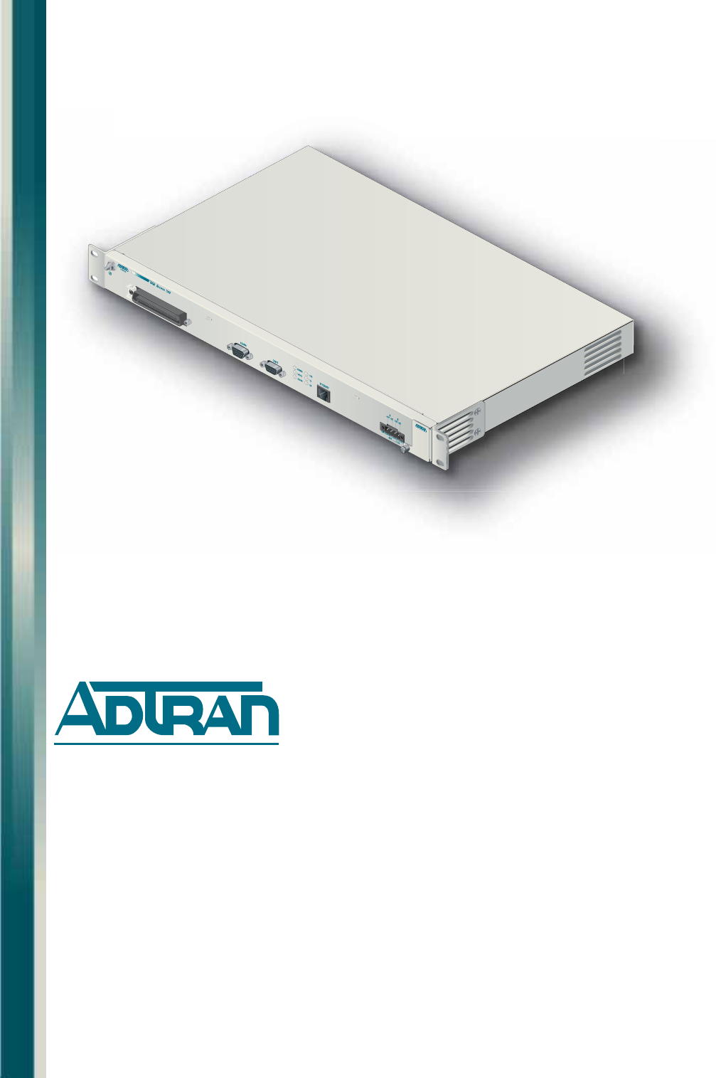
Section 1 Introduction GENERAL This practice is an installation and maintenance guide for the ADTRAN Total Access® 1240 2-wire/4-wire Single-pair High-speed Digital Subscriber Line (SHDSL) Digital Subscriber Line Access Multiplexer (DSLAM). Figure 1-1 illustrates the Total Access 1240 (P/N 1179605L5) front panel. Figure 1-1. Total Access 1240 Front Panel Description The Total Access 1240 is a 2-wire/4-wire SHDSL mini-DSLAM, consisting of 24 ports fed by a single 10/100Base-T Ethernet port.
Total Access 1240 Installation and Maintenance Practice Features The basic and security specific features of the Total Access 1240 are listed below.
Section 1, Introduction - General Front Panel LEDs There are six LEDs on the front panel of the Total Access 1240 (see Figure 1-2). Figure 1-2. Front Panel LEDs When power is applied the Total Access system performs the power up self-tests. Once the power up self-test is complete, the LEDs reflect the current condition of the hardware. The Total Access 1240 LEDs, status, and descriptions are provided in Table 1-1. Table 1-1.
Total Access 1240 Installation and Maintenance Practice Compliance The Total Access 1240 complies with the following international standards: • Safety – UL 60950 Third Edition; EN 60950 with IEC 950 CB Scheme • ETSI EN 300 386 V1.3.2 (2003-5) for other than telecommunications centres (Class B) • Environmental – Operational environment – NEBS GR-63-CORE; ETSI EN 300 019-1-3 Class 3.1E – Storage – NEBS GR-63-CORE; ETSI EN 300 019-1-1 class 1.
Section 2 Application Guidelines INTRODUCTION The Total Access 1240 operates as a transparent bridge to provide Medium Access Control (MAC) level bridging for Ethernet-like networks. The number of attached devices can be up to twenty-four 2-wire SHDSL modems or twelve 4-wire SHDSL modems or some combination thereof. When operating in the 4-wire SHDSL mode, if 2 wires are unavailable then the entire 4-wire circuit becomes Out of Service.
Total Access 1240 Installation and Maintenance Practice For security purposes, the unit operates such that Local Switching (Subscriber Port-to-Port Switching) can be disabled/enabled within the unit. Port-to-Port switching can also be accomplished using an external device such as an Ethernet Aggregation Switch. Destination MAC address filtering and Ether-type filtering are also implemented. The Total Access 1240 supports RFC 2684 (RFC 1483) Bridged Protocol Data Unit (PDU) only.
Section 2, Application Guidelines - VLAN Operation VLAN OPERATION A VLAN is a switched network that is logically segmented by function, project team, or application, without regard to the physical locations of the customers.
Total Access 1240 Installation and Maintenance Practice • Network – Egress – Every packet is forwarded. • Subscriber - Egress – The VLAN tag is removed. – The packet is forwarded to the VC corresponding to the original VLAN Tag. A diagram depicting the Total Access 1240 Ingress/Egress points is provided in Figure 2-2. Total Access 1240 Network Ingress Egress Egress Ingress Subscriber Figure 2-2.
Section 2, Application Guidelines - System Configuration Archive SYSTEM CONFIGURATION ARCHIVE The System Configuration Archive (SCA) (see Figure 2-3) is controlled by SNMP or screen selections to save provisioning information for the Total Access 1240 to a remote TFTP server for possible system restoration at a later time.
Total Access 1240 Installation and Maintenance Practice This page is intentionally blank.
Section 3 Installation INTRODUCTION C A U T I O N ! SUBJECT TO ELECTROSTATIC DAMAGE OR DECREASE IN RELIABILITY. HANDLING PRECAUTIONS REQUIRED. CAUTION Electronic units can be damaged by ESD. When handling a unit, wear an antistatic discharge wrist strap to prevent damage to electronic components. Place units in antistatic packing material when transporting or storing. When working on units, always place them on an approved antistatic mat that is electrically grounded.
Total Access 1240 Installation and Maintenance Practice Shipping Contents The shipping container for the Total Access 1240 includes the contents as shown in Table 3-1 Table 3-1.
Section 3, Installation - Mounting the Total Access 1240 MOUNTING THE TOTAL ACCESS 1240 The Total Access 1240 is shipped with two sets of mounting brackets that accommodate either a 19-inch or 21-inch rack. • The mounting brackets used for a 19-inch rack are part number 3265540-1. • The mounting brackets used for a 23-inch rack are part number 3265540-2. The mounting brackets provide for flush or mid-mounting configurations. Figure 3-1 shows the Total Access 1240 mounting bracket installation options.
Total Access 1240 Installation and Maintenance Practice Flush-mount For flush-mount systems, the Total Access 1240 must be mounted from the front of the rack, with mounting brackets in the flush-mounting orientation (see Figure 3-2). When flushmounting a Total Access 1240 in the rack, use a #2 phillips-head screwdriver and attach the mounting brackets to the front set of threaded screw holes with the flanges containing the slotted rack-mounting holes facing the front of the Total Access 1240.
Section 3, Installation - Mounting the Total Access 1240 Mid-mount For mid-mount systems, the Total Access 1240 must be mounted from the front of the rack, with mounting brackets in the mid-mounting orientation (see Figure 3-3). For mid-mounting a Total Access 1240 in the rack, use a #2 phillips-head screwdriver and attach the mounting brackets to the rear set of threaded screw holes with the flanges containing the slotted rackmounting holes facing the front of the Total Access 1240.
Total Access 1240 Installation and Maintenance Practice GROUND AND POWER CONNECTIONS The Total Access 1240 provides redundant power inputs. Two sources of –48 VDC must be provided to use the redundant power feature. The power wire must be 12 to 18 AWG stranded copper. The ground wire must be 12 to 18 AWG, however, it must be as large or larger than the wire used for power. Ground Connection The Total Access 1240 must be grounded to a reliable grounding source.
Section 3, Installation - Ground and Power Connections Power Connection The Total Access 1240 uses a four-point terminal block (see Figure 3-5) to accept the –48 VDC and –48 VDC RET leads. CA D 8V -4 -48 V A DC T RE B T RE DC V B C -48 VD 8 4 - Figure 3-5. Four-point Terminal Block NOTE If a non-redundant power configuration is to be implemented, use the connections marked –48 VDC A and –48 VDC A RET. To connect the power source, perform the following steps: 1.
Total Access 1240 Installation and Maintenance Practice Fans/Fan Filter The Total Access 1240 is shipped with a pre-installed fan module (P/N 1179672L1). The fan module is located on the right side of the unit and contains two fans (Figure 3-6). The fans move filtered air (if the filter is installed) into the Total Access 1240 chassis and out through the exhaust slots on the left side of the chassis.
Section 3, Installation - Ground and Power Connections Ethernet Connection The Total Access 1240 interfaces with networks through an Ethernet port. Figure 3-7 shows the location of the Ethernet port. Ethernet Connection Figure 3-7. Ethernet Port The following Ethernet protocols are supported: • IEEE 802.3, 10/100Base-T • IEEE 802.1Q • IEEE 802.
Total Access 1240 Installation and Maintenance Practice Alarm Connections The Total Access 1240 provides an alarm port (see Figure 3-8) with three auxiliary alarm inputs and three alarm outputs. Alarm inputs are activated by shorting A and B contacts which causes an alarm event. Alarm input events can be configured to one of four modes: Load Shedding, Major, Minor, or Critical and can be designated by the user. Load shedding can be used to reduce loading in the CO if needed.
Section 3, Installation - Ground and Power Connections SHDSL Connection The Total Access 1240 provides 24 SHDSL ports on one 50-pin male amphenol connector (see Figure 3-9). The 24 SHDSL links can be physically bonded in pairs. A maximum of twelve 4-wire SHDSL links are supported per module. SHDSL links are bonded in odd and even sequential pairs. For example, SHDSL links 1 and 2, 3 and 4, or 9 and 10 can be linked to form 4-wire SHDSL links. SHDSL Connection Figure 3-9.
Total Access 1240 Installation and Maintenance Practice This page is intentionally blank.
Section 4 Provisioning Defaults INTRODUCTION The Total Access 1240 can be provisioned by a set of menus that are accessible through the DB-9 port, labeled CRAFT, or through a management VLAN. The initial configuration of the system must be completed by way of one of these device ports. Once the management VLAN channel has been established, the system can be remotely managed through Telnet (IP), SNMP, or Total Access EMS. The Total Access 1240 default settings are shown in Table 4-1 through Table 4-5.
Total Access 1240 Installation and Maintenance Practice Table 4-1. Bridge User Port Default Provisioning Options (Continued) Provisioning Option Available Options Default Setting VLAN Priority 0 to 7 0 EtherType (ET) Any Any IP PPPoE Local Switching (LS) Enabled Disabled Disabled Destination Mac Filtering (DMF) Enabled Disabled Disabled Table 4-2.
Section 4, Provisioning Defaults - Introduction Table 4-3. SNMP Management Default Provisioning Options (Continued) Provisioning Option Available Options Default Setting (Static) Default Gateway 0–255.0–255.0–255.1–254 192.168.1.254 TFTP IP Address 0–255.0–255.0–255.0–255 192.168.1.2 IP VLAN ID 1 (untagged) 1 (untagged) 2 to 4094 (tagged) Test IP Address IP Address 0–255.0–255.0–255.0–255 Not configured Ping Timeout 1–10 seconds 1 second Number of Pings 1–8 pings 4 pings Time HH.
Total Access 1240 Installation and Maintenance Practice Table 4-4. User Port Default Provisioning Options (Continued) Provisioning Option Available Options Default Setting G.991.
Section 4, Provisioning Defaults - Introduction Table 4-5. SNMP Configuration Default Provisioning Options Provisioning Option Available Options Default Setting Contact 50-character string Customer specified Name 50-character string Location 50-character string SNMP Contact Information SNMP Community Names Name 52-character string Private Public Read/Write IP Address 0–255.0–255.0–255.
Total Access 1240 Installation and Maintenance Practice This page is intentionally blank.
Section 5 User Interface INTRODUCTION This section provides detailed information on the following: • “System Management” on page 5-1 • “Craft Interface” on page 5-1 • “Inband Management Interface” on page 5-2 • “Logging on to the Total Access 1240” on page 5-3 • “Menu Structure” on page 5-4 • “Menu Navigation” on page 5-5 • “Menu Trees” on page 5-6 • “Menu Descriptions” on page 5-9 SYSTEM MANAGEMENT Total Access 1240 system management and provisioning is facilitated by a series of intuitive menus that are
Total Access 1240 Installation and Maintenance Practice NOTE The craft port has priority over Telnet session. If there is an active craft port session, a Telnet session to the Total Access 1240 cannot be initiated. If there is an active Telnet session and a craft port session is initiated, the Telnet session is preempted. The Telnet session is not available until after the user at the craft port logs off or the auto-logoff occurs (after 10 minutes of inactivity).
Section 5, User Interface - Logging on to the Total Access 1240 LOGGING ON TO THE TOTAL ACCESS 1240 To login to the Total Access 1240 system, perform the following steps: 1. Establish the physical connection to the Total Access 1240. 2. If a craft port session is being used, proceed to step 3. If using a Telnet session proceed to step 4. 3. Press CTRL+R until the Login prompt appears. The Login screen is displayed in Figure 5-2. The Total Access 1240 system requires the login name and associated password.
Total Access 1240 Installation and Maintenance Practice MENU STRUCTURE The menu structure for the Total Access 1240 is a layered menu tree. Each layer of the menu tree is displayed as a menu or a screen. Menu A menu is a display that provides numbered selections that are used to navigate to related menus, modify provisioning information, or display information screens.
Section 5, User Interface - Menu Navigation MENU NAVIGATION Basic menu navigation is accomplished by selecting the desired option number and then pressing ENTER. To return to the previous menu or screen, press the ESC (escape) key. To access the System Help screen, press the question mark (?) key, and press ENTER. Hot Keys Table 5-1 shows the general keyboard commands and Table 5-2 shows the menu specific hot keys for the Total Access 1240 system. Table 5-1.
Total Access 1240 Installation and Maintenance Practice Table 5-2. Menu Specific Hot Keys (Continued) Hot Key Description System Alarms A This hot key is used to acknowledge all alarms. C This hot key is used to clear all alarms. F This hot key is used to display the first alarm. L This hot key is used to display the last alarm. N This hot key is used to display the next alarm. P This hot key is used to display the previous alarm. R This hot key is used to reset all alarm logs.
Section 5, User Interface - Menu Trees 1. Unit Information Unit Name Part Number Serial Number Product Revision Software Revision 1. Bridge Port Provisioning Bridge Port Summary 2. Bridge Circuit Management 1. Port 2. Bridge 3. Circuit ID 4. VPI 5. VCI 6. Priority 7. Select Destination Mac Filters 8. VLAN ID 9. VLAN Priority 10. Ether Type 11. Local Switching 12. Enabled/Disabled 13. Save Changes 14. Apply to Other Ports 1. Duplex Mode 2. Ethernet Provisioning 2. Speed 3. Ethernet Statistics 4.
Total Access 1240 Installation and Maintenance Practice 1. Password Control B 2. IP Address 1. Set Passwords 2. Allow SNMP Security Management 3. Set Idle Logout Time 4. Restore Default Passwords IP Feed 2. Mode 1. Static 2. Dynamic (Static IP Settings) 3. Configure IP 3. Test IP Address 4. Time/ Date 5. Baud Rate 6. System Configuration Archive 1. IP Address 2. Ping Timeout 3. Number of Pings 4. Start Ping 5. Start Traceroute 2. Community Names 3. Trap Hosts 4. Traps Enabled 1. Alarm 1 2.
Section 5, User Interface - Menu Descriptions MENU DESCRIPTIONS The Total Access 1240 Main menu (see Figure 5-5) is the access point to all other operations. The Main menu options have several functions and submenus that identify and provide access to specific operations and parameters. Total Access 1240 - IPoE Fed 09/01/05 03:40 Unacknowledged Alarms: None Total Access 1240 1. 2. 3. 4. 5. 6. 7.
Total Access 1240 Installation and Maintenance Practice Configuration Screen The Configuration screen (see Figure 5-6) displays information about the system. For instance, the part number can be used to search for related information on the ADTRAN website or to order additional parts. The software revision can be required when calling ADTRAN Technical Support.
Section 5, User Interface - Menu Descriptions Bridge Circuit Management Menu The Bridge Circuit Management menu (see Figure 5-7) is used to provision and maintain customer circuits and the Ethernet circuit feeding the system. Total Access 1240 - IPoE Fed 09/01/05 03:41 Unacknowledged Alarms: None Bridge Circuit Management 1. 2. 3. 4. Bridge Port Provisioning Ethernet Provisioning Ethernet Statistics Bridge Port Statistics Selection: '?' - System Help Screen Figure 5-7.
Total Access 1240 Installation and Maintenance Practice Bridge Port Summary Screen The Bridge Port Summary screen (see Figure 5-8) displays all ports and their set parameters simultaneously. A highlighted port number on this screen indicates a modem as online and trained. To provision a specific port, navigate to the port with directional arrows, and press the spacebar (Refer to “Bridge User Port Provisioning Menu” on page 5-13).
Section 5, User Interface - Menu Descriptions Bridge User Port Provisioning Menu The Bridge User Port Provisioning menu (see Figure 5-9) displays the bridge provisioning for the port selected from the Bridge Port Provisioning Summary screen (see Figure 5-8 on page 512) and is used to set up and maintain the 24 ports.
Total Access 1240 Installation and Maintenance Practice The Bridge User Port Provisioning menu options are shown in Table 5-8. Table 5-8. Bridge User Port Provisioning Menu Options Option Description Function 1 Port This option is used select a Port (1-24). 2 Bridge This option is used to assign a bridge number to each circuit. Each circuit must be assigned to one of four bridges.
Section 5, User Interface - Menu Descriptions Strict Prioritization There are four available virtual circuits (VCs) per SHDSL loop that can be prioritized on a strict prioritization basis. This means that any available high priority VC traffic gets queued into the ATM/SHDSL pipe first followed by traffic at the next highest priority class, and so on, to the lowest priority class (see Figure 5-10). If a priority class contains no elements, it is bypassed but always considered for the next queueing sequence.
Total Access 1240 Installation and Maintenance Practice VLAN Priority The VLAN Priority option is used to prioritize traffic up to eight levels, with 0 as the lowest and 7 as the highest priority. Table 5-9 lists an example of how traffic types might be organized in a network implementation. Table 5-9.
Section 5, User Interface - Menu Descriptions EtherType Filtering The EtherType Filtering option (see Figure 5-11) allows filtering of the ingress/egress traffic of the subscriber ports based on the ethertype of IP or PPPoE. This option is applicable on a per VC basis. • Packets are filtered based on the following EtherTypes: – IP – PPPoE – Any Ethernet Egress Ingress • Packets that do not meet the provisioned EtherType are discarded. Total Access 1240 Either packet type is forwarded.
Total Access 1240 Installation and Maintenance Practice Local Switching Ethernet Egress Ingress The Local Switching option (see Figure 5-12) allows subscriber to subscriber traffic when it is enabled and both subscribers are on the same VLAN. The data is forwarded to the correct port as determined by the MAC Learning Table. This option is applied on a per VC basis.
Section 5, User Interface - Menu Descriptions Router Dest Mac Filtering Menu Ethernet Egress Ingress The Select Destination Mac Filters option from the Bridge User Port Provisioning Menu (refer to “Bridge User Port Provisioning Menu” on page 5-13) allows filtering of ingress traffic of the subscriber ports based on the configured Mac addresses (see Figure 5-13).
Total Access 1240 Installation and Maintenance Practice The Router Dest Mac Filtering Menu (see Figure 5-14) is used to select a Port and Bridge, enable or disable MAC filtering, and set up to 5 MAC Addresses. Total Access 1240 - IPoE Fed Unacknowledged Alarms: None Router Dest Mac Filtering 1. 2. 3. 4. 5. 6. 7. 8. 9.
Section 5, User Interface - Menu Descriptions Apply Provisioning to Ports Menu The Apply Provisioning to Ports menu (see Figure 5-15) is used to apply any provisioning changes to more than one port. Any number of ports can be selected to apply provisioning. Total Access 1240 - IPoE Fed Unacknowledged Alarms: None Apply Provisioning to Ports Warning! This is service affecting! This will copy the following options to the ports you enter! Port Bridge 1. 1 1. 2 1. 3 1.
Total Access 1240 Installation and Maintenance Practice Table 5-12. Apply Provisioning to Ports Menu Fields Field Description Port This field displays the port number to be provisioned. Bridge This field displays the bridge number to be provisioned. VPI This field displays the VPI assigned to port. VCI This field displays the VCI assigned to port. PRI This field displays the traffic priority setting. VLAN This field displays the VLAN assigned to port.
Section 5, User Interface - Menu Descriptions Ethernet Provisioning Menu The Ethernet Provisioning menu (see Figure 5-16) is used to configure the Ethernet port. The Ethernet port is used to connect the Total Access 1240 to a network. Total Access 1240 - IPoE Fed 09/01/05 03:44 Unacknowledged Alarms: None Ethernet Provisioning 1. Duplex Mode 2. Speed Full Duplex 100Base Selection : Ethernet Link: Not Active '?' - System Help Screen Figure 5-16.
Total Access 1240 Installation and Maintenance Practice Duplex Mode Menu The Duplex Mode menu (see Figure 5-17) is used to select the duplex mode of the Ethernet interface. Total Access 1240 - IPoE Fed 09/01/05 03:44 Unacknowledged Alarms: None Duplex Mode - Full Duplex 1. Auto Negotiate 2. Full Duplex 3. Half Duplex Selection : '?' - System Help Screen Figure 5-17. Duplex Mode Menu NOTE The duplex mode displayed in the title indicates the current duplex mode being viewed or provisioned.
Section 5, User Interface - Menu Descriptions Speed Mode Menu The Speed Mode menu (see Figure 5-18) provides options to choose the Ethernet speed. Total Access 1240 - IPoE Fed 09/01/05 03:44 Unacknowledged Alarms: None Speed Mode - 100Base 1. Auto Negotiate 2. 100Base 3. 10Base Selection : '?' - System Help Screen Figure 5-18. Speed Mode Menu NOTE The speed mode displayed in the title indicates the current speed mode being viewed or provisioned.
Total Access 1240 Installation and Maintenance Practice Current Ethernet Statistics Menu The Current Ethernet Statistics menu (see Figure 5-19) is used to view and reset the current Ethernet statistics.
Section 5, User Interface - Menu Descriptions The Current Ethernet Statistics menu hot keys are shown in Table 5-17. Table 5-17. Current Ethernet Statistics Menu Hot Keys Hot Key Description C This hot key is used to clear the current Ethernet statistics. J This hot key displays the “Previous Ethernet Statistics Menu” on page 5-28.
Total Access 1240 Installation and Maintenance Practice Previous Ethernet Statistics Menu The Previous Ethernet Statistics menu (see Figure 5-20) is used to view the previous five 15minute periods of Ethernet statistics.
Section 5, User Interface - Menu Descriptions The Previous Ethernet Statistics menu fields are described in Table 5-19. Table 5-19. Ethernet Statistics - Previous Fields Field Description Successful Tx Packets This field displays the number of packets successfully transmitted from the unit. Errored Tx Packets This field displays the number of packets transmitted with errors from the unit. Successful Rx Packets This field displays the number of packets successfully received to the unit.
Total Access 1240 Installation and Maintenance Practice Current Bridge Statistics Menu The Current Bridge Statistics menu (see Figure 5-21) is used to select a bridge and view and reset current port statistics. NOTE On the Current Bridge Statistics menu, Transmit Statistics refers to data from the Total Access 1240 to the customer modem, and Receive Statistics refers to data from the customer modem to the Total Access 1240.
Section 5, User Interface - Menu Descriptions Table 5-22. Current Bridge Statistics Menu Fields Field Description Transmit Statistics Good Packets This field displays the number of good packets successfully transmitted by the Total Access 1240. Bad Packets This field displays the number of bad packets transmitted by the Total Access 1240. Good Bytes This field displays the number of good bytes successfully transmitted by the Total Access 1240.
Total Access 1240 Installation and Maintenance Practice Previous Bridge Statistics Menu The Previous Bridge Statistics menu (see Figure 5-22) is used to view previous bridge transmit and receive statistics.
Section 5, User Interface - Menu Descriptions The Previous Bridge Statistics menu fields are described in Table 5-25. Table 5-25. Previous Bridge Statistics Menu Fields Field Description Successful Tx Packets This option displays the number of packets successfully transmitted from the unit. Errored Tx Packets This option displays the number of packets transmitted with errors from the unit. Successful Tx Bytes This option displays the number of bytes successfully transmitted from the unit.
Total Access 1240 Installation and Maintenance Practice System Management Menu The System Management menu (see Figure 5-23) is used to manage system wide settings. The following subsections describe these settings in detail. Total Access 1240 - IPoE Fed 09/01/05 03:48 Unacknowledged Alarms: None System Management 1. 2. 3. 4. 5. 6. 7. 8. 9. 10. 11.
Section 5, User Interface - Menu Descriptions Table 5-27. System Management Menu Options (Continued) Option Description Function 8 External Alarms This option displays the “External Alarms Menu” on page 5-57. 9 Download New Code This option displays the “Code Download Method Menu” on page 5-59. 10 Restore Factory Defaults This option displays the “Restore Factory Defaults Menu” on page 5-63. 11 Reset System This option displays the “Reset System Menu” on page 5-64.
Total Access 1240 Installation and Maintenance Practice Password Control Menu The Password Control menu (see Figure 5-24) is used to set and modify passwords, logout times, and restore default passwords. Total Access 1240 - IPoE Fed Unacknowledged Alarms: None Password Control 1. 2. 3. 4. Set Passwords Allow SNMP security management Set Idle Logout Time Restore Default Passwords None Configured Disabled 10 minutes Selection : '?' - System Help Screen Figure 5-24.
Section 5, User Interface - Menu Descriptions Password Control Levels Screen The Password Control Levels screen (see Figure 5-25) is used to manage User IDs and associated passwords that access the system. Total Access 1240 - IPoE Fed Unacknowledged Alarms: None User Read Only Technician System Administrator Password Control Levels Status Login Not Configured ? Configured Technician Configured ADMIN Press space bar to set/change login Figure 5-25.
Total Access 1240 Installation and Maintenance Practice Set or Change Username or Password To set or change a username or password, perform the following steps: 1. Navigate to a Username field with the arrow keys. The Username field displays in reverse video. 2. Press the spacebar to open the field, type a username, and press ENTER. 3. Press the TAB key to navigate to the Password field. The Password field displays in reverse video. 4. Press the spacebar to open the field, type a password, and press ENTER.
Section 5, User Interface - Menu Descriptions Mode Selection and Current IP Settings Menu The Mode Selection and Current IP Settings menu (see Figure 5-26) is used to configure IP settings in order to remotely manage the Total Access 1240 system. Total Access 1240 - IPoE Fed Unacknowledged Alarms: None Mode Selection and Current IP Settings IP Feed 2. Mode 3.
Total Access 1240 Installation and Maintenance Practice Table 5-30.
Section 5, User Interface - Menu Descriptions Table 5-31. Static IP Settings - for IP over Ethernet Menu Options Option Description Function 1 IP address This options is used to configure the IP address in decimal dot format (i.e., ###.###.###.###). 2 Subnet mask This option is used to configure the Subnet Mask in decimal dot format. 3 Default Gateway This option is used to configure the Default Gateway.
Total Access 1240 Installation and Maintenance Practice Restore IP Factory Defaults Menu The Restore IP Factory Defaults menu (see Figure 5-28) is used to reset all of the IP factory defaults. CAUTION This is service affecting. If IP factory defaults are enabled remotely, IP connectivity is lost. Total Access 1240 - IPoE Fed 09/01/05 03:52 Unacknowledged Alarms: None Restore IP Factory Defaults 1. Yes - Service Affecting Selection : '?' - System Help Screen Figure 5-28.
Section 5, User Interface - Menu Descriptions Dynamic IP Settings - for IP over Ethernet Menu The Dynamic IP Settings - for IP over Ethernet menu (see Figure 5-29) is used to provision some of the IP settings. When the Mode option is set to Dynamic, the Total Access 1240 system automatically retrieves the IP address, Subnet mask, and Default Gateway from the remote DHCP server. The remaining menu items can be provisioned manually.
Total Access 1240 Installation and Maintenance Practice Restore IP Factory Defaults Menu The Restore IP Factory Defaults menu (see Figure 5-30) is used to reset all of the IP factory defaults. CAUTION This is service affecting. If IP factory defaults are enabled remotely, IP connectivity is lost. Total Access 1240 - IPoE Fed 04/01/05 08:09 Unacknowledged Alarms: None Restore IP Factory Defaults 1. Yes - Service Affecting Selection : '?' - System Help Screen Figure 5-30.
Section 5, User Interface - Menu Descriptions Test IP Address Menu The Test IP Address menu (see Figure 5-31) is used to test IP configurations. Ping and Traceroute utilities are includes in this menu. Total Access 1240 - IPoE Fed Unacknowledged Alarms: None Test IP Address 1. IP Address 2. Ping Timeout 3. Number of Pings Not configured 1 secs 4 pings 4. Start Ping 5. Start Traceroute Selection : '?' - System Help Screen Figure 5-31.
Total Access 1240 Installation and Maintenance Practice Time/Date Adjust Menu The Time/Date Adjust menu (see Figure 5-32) is used to set the system time and date and configure Simple Network Management Protocol (SNTP) client settings. The time and date appears on most screens and is also used for performance monitoring displays. Total Access 1240 - IPoE Fed Unacknowledged Alarms: None Time/Date Adjust 1. 2. 3. 4. 5. 6. Adjust Time Adjust Date SNTP: Status SNTP: Server Addr. SNTP: Poll Int.
Section 5, User Interface - Menu Descriptions Table 5-34. Time/Date Adjust Menu Options (Continued) Option 6 Description Function SNTP: Timezone This option is used to select a specific time zone for SNTP capabilities. The time zone is based from the GMT and a valid input can be offset from –12 to 13 hours from GMT.
Total Access 1240 Installation and Maintenance Practice Current Baud Rate Menu The Current Baud Rate menu (see Figure 5-33) displays the current baud rate. The default management port baud rate is 9600 bps. Total Access 1240 - IPoE Fed 09/01/05 03:54 Unacknowledged Alarms: None Current Baud Rate: 9600 Baud Rate change is instantaneous, remember to adjust your terminal 1. 9600 2. 19200 3. 38400 Selection : '?' - System Help Screen Figure 5-33.
Section 5, User Interface - Menu Descriptions System Configuration Archive Screen The System Configuration Archive (SCA) Screen (see Figure 5-34) is used to save/retrieve provisioning information for the Total Access 1240 to/from a remote TFTP server for possible system restoration at a later time. Total Access 1240 - IPoE Fed Unacknowledged Alarms: None System Configuration Archive TFTP Server: 10.200.200.
Total Access 1240 Installation and Maintenance Practice Table 5-36. System Configuration Archive Screen Fields (Continued) Field Description Error Status This field displays the status of the TFTP transfer. The Error Status messages are as follows: • File Not Found: This status indicates that the TFTP network server was unable to locate the specified file name or path in the TFTP Server Filename field.
Section 5, User Interface - Menu Descriptions SNMP Configuration Menu The SNMP Configuration menu (see Figure 5-35) is used to provision community names, trap hosts, and the traps enabled options, which provide control to manage SNMP remote access to the system through inband management. Total Access 1240 - IPoE Fed 09/01/05 03:54 Unacknowledged Alarms: None SNMP Configuration 1. 2. 3. 4.
Total Access 1240 Installation and Maintenance Practice SNMP Contact Information Menu The SNMP Contact Information menu (see Figure 5-36) contains contact information and can be customized to reflect any contact, name and location. Total Access 1240 - IPoE Fed Unacknowledged Alarms: None SNMP Contact Information 1. Contact 2. Name 3. Location ADTRAN, Inc. (256)963-8000 Selection : '?' - System Help Screen Figure 5-36.
Section 5, User Interface - Menu Descriptions SNMP Community Names Menu The SNMP Community Names menu (see Figure 5-37) is used to establish up to three named accounts which specify unique IP addresses and privileges for network management. To restrict SNMP remote access to a single IP address, assign the IP address to a community. An IP address of 0.0.0.0 provides access from all IP addresses. Total Access 1240 - IPoE Fed Unacknowledged Alarms: None 1. Name 2. 3. 4. Name 5. 6. 7. Name 8. 9.
Total Access 1240 Installation and Maintenance Practice Table 5-39. SNMP Community Names Menu Options (Continued) Option 5-54 Description Function 6 Privileges This option is used to configure the second SNMP community privilege level. Options include Read/Write and Read. 7 Name This option is used to configure the third SNMP community. Settings include Private and Public. 8 IP Address This option is used to configure the third SNMP community IP address in decimal dot format (i.e., ###.###.###.
Section 5, User Interface - Menu Descriptions SNMP Trap Hosts Menu The SNMP Trap Hosts menu (see Figure 5-38) is used to set multiple IP Addresses (trap destinations) and SNMP versions for notification of a trap. A trap is an automatic alert, or notification, sent to an IP Address. The Total Access 1240 system forwards SNMP traps to all configured hosts as the traps occur. Total Access 1240 - IPoE Fed Unacknowledged Alarms: None SNMP Trap Hosts Set IP address to enter Trap Host.
Total Access 1240 Installation and Maintenance Practice Table 5-40. SNMP Trap Hosts Menu Options (Continued) Option 4 Description Function Version This option is used to configure the SNMP version for the second SNMP trap host. Options include the following: • SNMPv1 • SNMPv2 5 IP Address This option is used to configure the third SNMP trap host IP address in decimal dot format (i.e., ###.###.###.###). 6 Version This option is used to configure the SNMP version for the third SNMP trap host.
Section 5, User Interface - Menu Descriptions External Alarms Menu The External Alarms menu (see Figure 5-39) is used to customize the profiles for up to three external alarms. The alarms can be assigned unique names and an associated severity level (refer to “External Alarm Severity Menu” on page 5-58). Total Access 1240 - IPoE Fed Unacknowledged Alarms: None External Alarms 1. Alarm #1 Text - External Alarm Input #1 2. Alarm #2 Text - External Alarm Input #2 3.
Total Access 1240 Installation and Maintenance Practice External Alarm Severity Menu The External Alarm Severity menu (see Figure 5-40) is used to set customized alarm profiles for each of the five external alarms. Total Access 1240 - IPoE Fed 09/01/05 03:55 Unacknowledged Alarms: None External Alarm Severity 1. 2. 3. 4. Critical Major Minor Load Shedding Selection : '?' - System Help Screen Figure 5-40. External Alarm Severity Menu The External Alarm Severity menu options are shown in Table 5-42.
Section 5, User Interface - Menu Descriptions Code Download Method Menu The Code Download Method menu (see Figure 5-41) displays two methods to download code: • Y-Modem • TFTP CAUTION Downloading new code is service affecting. NOTE The System Management menu TFTP IP address option must be configured to use TFTP. Total Access 1240 - IPoE Fed 09/01/05 03:55 Unacknowledged Alarms: None Code Download Method 1. Y-Modem (Craft Port) 2. TFTP Selection : '?' - System Help Screen Figure 5-41.
Total Access 1240 Installation and Maintenance Practice Y-Modem Download Menu The Y-Modem Download menu (see Figure 5-42) is used to download code stored from a computer to the Total Access 1240 through the craft port. Total Access 1240 - IPoE Fed 09/01/05 03:56 Unacknowledged Alarms: None WARNING! THIS IS SERVICE AFFECTING! If either Flash A or B is selected for update, service is affected. If Flash B is selected, and code download completes, the unit will restart itself to implement the new code.
Section 5, User Interface - Menu Descriptions TFTP Firmware Download Screen The TFTP Firmware Download screen (see Figure 5-43) is used to download code stored from a computer to the Total Access 1240 through a TFTP server. Total Access 1240 - IPoE Fed Unacknowledged Alarms: None TFTP Firmware Download TFTP Server: 10.200.200.218 Get Code for: 1179605L5_A_*** Flash A TFTP Filename: Error Status: Update progress: Press Space bar to enter TFTP address Figure 5-43.
Total Access 1240 Installation and Maintenance Practice Table 5-44. TFTP Firmware Download Screen Fields (Continued) Field Description Update Progress This field displays the progress of the TFTP download. Progress messages are as follows: • Contacting Server: This message indicates that an attempt to establish communication with the TFTP network server specified by the server address in the TFTP Server IP Address field is in progress.
Section 5, User Interface - Menu Descriptions Restore Factory Defaults Menu The Restore Factory Defaults menu (see Figure 5-44) is used to remotely restore the factory defaults of the system. CAUTION This action is service affecting. If the system is accessed remotely through a static IP address, the system resets and access is lost.
Total Access 1240 Installation and Maintenance Practice Reset System Menu The Reset System menu (see Figure 5-45) is used to remotely reset the system. CAUTION This action is service affecting. If the system is accessed remotely through a static IP address, the system resets and access is lost. CAUTION When the Reset System option is selected, the system resets without additional prompting.
Section 5, User Interface - Menu Descriptions SHDSL Ports Menu The SHDSL Ports menu (see Figure 5-46) is used to provision all SHDSL ports. 09/01/05 03:56 Total Access 1240 SHDSL Ports 1. 2. 3. 4. 5. 6. 7. Configuration Provisioning Status Alarms Test Performance Remote Terminal Selection: '?' - System Help Figure 5-46. SHDSL Ports Menu The SHDSL Ports menu options are shown in Table 5-47. Table 5-47.
Total Access 1240 Installation and Maintenance Practice SHDSL Loop 1 Configuration Screen The SHDSL Loop 1 Configuration screen (see Figure 5-47) displays information about the system. For instance, the part number can be used to search for related information on the ADTRAN website or to order additional parts. The software revision can be required when calling ADTRAN Technical Support.
Section 5, User Interface - Menu Descriptions Table 5-48. SHDSL Loop 1 Configuration Fields Field LTU Description NTU Description Vendor ID This field displays the unit vendor ID. This field displays the modem vendor ID. Part Number This field displays the part number of the unit. This field displays the part number of the modem. Serial Number This field displays the serial number of the unit. This field displays the serial number of the modem.
Total Access 1240 Installation and Maintenance Practice Provisioning Menu The Provisioning menu (see Figure 5-48) is used to set the provisioning for the main circuit board card or the SHDSL Circuit IDs. 09/01/05 03:57 Total Access 1240 Provisioning 1. 2. Card SHDSL Selection: '?' - System Help Figure 5-48. Provisioning Menu The Provisioning menu options are shown in Table 5-49. Table 5-49.
Section 5, User Interface - Menu Descriptions Card Provisioning Menu The Card Provisioning menu (see Figure 5-49) is used to set the service state of the main circuit board card. The default value for the Card Service State is Out of Service-Maintenance. Changes to this service state are reflected on all 24 ports. 09/01/05 03:58 Total Access 1240 Card Provisioning 1. 2. Service State = OOS-Maintenance Restore Factory Defaults Selection: '?' - System Help Figure 5-49.
Total Access 1240 Installation and Maintenance Practice Restore Factory Defaults Screen The Restore Factory Defaults screen (see Figure 5-50) is used to restore the factory defaults of the main circuit board card. CAUTION This action is service affecting. If the system is accessed remotely through a static IP address, the system resets and access is lost.
Section 5, User Interface - Menu Descriptions SHDSL Loop 1 Provisioning Menu The SHDSL Loop 1 Provisioning menu (see Figure 5-51) is used to provision all of the SHDSL Circuit IDs. A Circuit ID is initially named using the SHDSL Loop 1 Service State Menu option from the Bridge Port Summary Screen menu. 09/01/05 01:34 Total Access 1240 SHDSL Loop 1 Provisioning 1. 2. 3. 4. 5. 6. 7. 8. Service State Interface Mode Rate G.991.
Total Access 1240 Installation and Maintenance Practice SHDSL Loop 1 Service State Menu The SHDSL Loop 1 Service State menu (see Figure 5-52) is used to set the loop service state. The default value is Out of Service-Maintenance. 09/01/05 03:58 Total Access 1240 SHDSL Loop 1 Service State 1. 2. 3. In Service Out of Service - Unassigned Out of Service - Maintenance Selection: '?' - System Help Figure 5-52.
Section 5, User Interface - Menu Descriptions SHDSL Loop 1 Interface Mode Menu The SHDSL Loop 1 Interface Mode menu (see Figure 5-53) is used to set the interface mode. The interface mode can be set to either 2-wire or 4-wire. SHDSL transceivers are designed primarily for duplex operation over mixed gauge 2-wire twisted metallic pairs, however, optional 4-wire operation is supported for extended reach applications. 09/01/05 03:59 Total Access 1240 SHDSL Loop 1 Interface Mode 1. 2.
Total Access 1240 Installation and Maintenance Practice SHDSL Loop 1 Rate Screen The SHDSL Loop 1 Rate screen (see Figure 5-54) is used to set the rate for the Circuit ID. 09/01/05 03:09 Total Access 1240 SHDSL Loop 1 Rate Enter a value for N from 3 to 36, where the payload rate = N x 64 Kbps: '?' - System Help Figure 5-54. SHDSL Loop 1 Rate Screen The rates defined in SHDSL standard G.991.2 are N × 64 kbits/s, where N = 3 (192 kb/s) to 36 (2304 kb/s).
Section 5, User Interface - Menu Descriptions SHDSL Loop 1 G.991.2 Annex Menu The SHDSL Loop 1 G.991.2 Annex menu (see Figure 5-55) is used to select the annex for the SHDSL loop. 09/01/05 03:10 Total Access 1240 SHDSL Loop 1 G.991.2 Annex 1. 2. 3. A B A/B Selection: '?' - System Help Figure 5-55. SHDSL Loop 1 G.991.2. Annex Menu The SHDSL Loop 1 G.991.2 Annex menu options are shown in Table 5-54. Table 5-54. SHDSL Loop 1 G.991.
Total Access 1240 Installation and Maintenance Practice SHDSL Loop 1 LineProbing Menu The SHDSL Loop 1 LineProbing menu (see Figure 5-56) is used to configure the Total Access 1240 line probe feature which performs a sequence of power measurements on the twisted pair. From these measurements, the Total Access 1240 determines what the maximum line rate is that it can connect at. Another name for line probe is Power Measurement Modulation Session (PMMS).
Section 5, User Interface - Menu Descriptions SHDSL Loop 1 PMMS Margin Screen The SHDSL Loop 1 PMMS Margin Screen (see Figure 5-57 and Figure 5-58) is used to specify the PMMS Margin in units of dB. The PMMS Margin selection modifies the line probe algorithm to maximize the rate against the specified margin. 09/01/05 03:07 Total Access 1240 SHDSL Loop 1 PMMS Margin Enter a Current Condition Margin value for N from 0 to 20, in dB '?' - System Help Figure 5-57.
Total Access 1240 Installation and Maintenance Practice SHDSL Loop 1 Alarm Thresholds Menu The SHDSL Loop 1 Alarm Thresholds menu (see Figure 5-59) is used to enable, disable, or set the thresholds for each interval. When set, each threshold dictates the level or number of alarm counts at which an SNMP trap is sent. 09/01/05 03:10 Total Access 1240 SHDSL Loop 1 Alarm Thresholds 1. 2. 3. 4. 5. 6. 7.
Section 5, User Interface - Menu Descriptions Table 5-56. SHDSL Loop 1 Alarm Threshold Menu Options (Continued) Option Alarm Threshold Description 4 SES 15 Minute This option is used to enable or disable the Severely Errored Second setting. SES 15 minute threshold is a count of 1-second intervals during which at least 50 CRC anomalies are declared or one or more LOSW defects are declared. 50 CRC anomalies during a 1-second interval are equivalent to a 30% errored frame rate for a nominal frame length.
Total Access 1240 Installation and Maintenance Practice SHDSL Loop 1 Status Menu The SHDSL Loop 1 Status menu (see Figure 5-60) is used to view and reset SHDSL port status information. 09/01/05 03:03 Total Access 1240 SHDSL Loop 1 Status General Status : Down Payload Rate : N/A Loopback Status SNR Margin(dB) Loop Atten(dB) ES SES UAS LOSWS CVC Interface Mode : 2-wire : : : : : : : : LTU Inactive N/A,N/A,N/A N/A,N/A,N/A 0 0 1647 1647 0 1.
Section 5, User Interface - Menu Descriptions Table 5-57. SHDSL Loop 1 Status Menu Fields (Continued) Field LTU Description NTU Description Loopback Status This field displays the loopback status of the unit. This field displays the loopback status of the modem. SNR Margin (dB) This field displays the received signal level compared to noise level from the unit. This field displays the received signal level compared to noise level from the SHDSL modem.
Total Access 1240 Installation and Maintenance Practice Alarm Status Screen The Alarm Status screen (see Figure 5-61) is used to view and clear the alarm log.
Section 5, User Interface - Menu Descriptions SHDSL Loop 1 Test Menu The SHDSL Loop 1 Test menu (see Figure 5-62) is used to set testing for the SHDSL local or remote loopbacks. 09/01/05 03:14 Total Access 1240 SHDSL Loop 1 Test 1. 2. Local Loopback Remote Loopback : Inactive : N/A Selection: 'N' - Next Loop 'P' - Prev Loop 'S' - Select Loop '?' - System Help Figure 5-62. SHDSL Loop 1 Test Menu The SHDSL Loop 1 Test menu options are shown in Table 5-58. Table 5-58.
Total Access 1240 Installation and Maintenance Practice SHDSL Loop 1 Local Loopback Menu The SHDSL Loop 1 Local Loopback menu (see Figure 5-63), is used to perform and view local loopback tests. For troubleshooting purposes, the Total Access 1240 provides three types of local loopbacks: • Dual-Sided • Customer • Network 09/01/05 03:05 Total Access 1240 SHDSL Loop 1 Local Loopback 1. 2. 3.
Section 5, User Interface - Menu Descriptions Local Dual-Sided Loopback The local dual-sided loopback provides a bidirectional loopback at the Line Termination Unit (LTU), as shown in Figure 5-64. LTU NTU Figure 5-64. Local Dual-Sided Loopback Local Customer Loopback The local customer loopback provides a loopback at the LTU in the customer direction, as shown in Figure 5-65. An Alarm Indication Signal (AIS) is injected into the network side. LTU TX AIS NTU Figure 5-65.
Total Access 1240 Installation and Maintenance Practice SHDSL Loop 1 Remote Loopback Menu The SHDSL Loop 1 Remote Loopback menu (see Figure 5-67), is used to perform and view remote loopback tests. For troubleshooting purposes, the Total Access 1240 provides three types of remote loopbacks: • Dual-Sided • Customer • Network 09/01/05 00:06 Total Access 1240 SHDSL Loop 1 Remote Loopback 1. 2. 3.
Section 5, User Interface - Menu Descriptions Remote Dual-Sided Loopback The remote dual-sided loopback provides a bidirectional loopback at the Network Termination Unit (NTU), as shown in Figure 5-68. LTU NTU Figure 5-68. Remote Dual-Sided Loopback Remote Customer Loopback The remote customer loopback provides a loopback at the NTU in the customer direction, as shown in Figure 5-69. An Alarm Indication Signal (AIS) is injected into the network side. LTU NTU TX AIS Figure 5-69.
Total Access 1240 Installation and Maintenance Practice SHDSL Loop 1 Performance Screen The SHDSL Loop 1 Performance screen (see Figure 5-71) provides information on loop errors in current and previous 15 minute and 24 hour time intervals.
Section 5, User Interface - Menu Descriptions System Alarm Log Screen The System Alarm Log screen (see Figure 5-72) provides non-volatile storage of system events. The event logs can be sorted in ascending or descending order.
Total Access 1240 Installation and Maintenance Practice Contact Information Screen The Contact Information screen (see Figure 5-73) displays ADTRAN technical support, repair, and online support contact information. Total Access 1240 - IPoE Fed 09/01/05 03:16 Unacknowledged Alarms: None Contact Information Adtran Technical Support: (800)726-8663 Adtran Repair / CAPS: (256)963-8722 Online Support: www.adtran.com '?' - System Help Screen Figure 5-73.
Section 6 Maintenance INTRODUCTION The Total Access 1240 does not require routine maintenance for normal operation. ADTRAN does not recommend that repairs be attempted in the field. Repair services can be obtained by returning the defective unit to ADTRAN. Refer to the “Appendix C, Warranty” section for further information.
Total Access 1240 Installation and Maintenance Practice This page is intentionally blank.
Section 7 Specifications INTRODUCTION Specifications for the Total Access 1240 are detailed in Table 7-1. Table 7-1. Total Access 1240 Specifications Specifications Descriptions Environmental Operating Temperature: –40°C to +70°C Storage Temperature: –40°C to +85°C Relative Humidity: Maximum Current Draw: Maximum Heat Dissipation: 95 percent maximum at 50°C, non-condensing 0.625 amps maximum at –48 VDC 30 watts Physical Dimensions: Height: 44.45 millimeters; 1.
Total Access 1240 Installation and Maintenance Practice This page is intentionally blank.
Appendix A Declaration of Conformity Corporate Office • 901 Explorer Blvd. • P.O. Box 140000 • Huntsville, AL 35814-4000 • (205) 963-8000 Declaration of Conformity Adtran 901 Explorer Boulevard Huntsville Alabama, USA Declares that the product: TA1240 24 Port 2W/4W SHDSL DSLAM 1179605L5 is in conformity with the following directives and standards; Electromagnetic Compatibility Directive, 89/336/EEC, as amended by 92/31/EEC, 93/68/EEC, EN 300 386 V.1.3.
Total Access 1240 Installation and Maintenance Practice This page is intentionally blank.
Appendix B SCA File Format SCA FORMAT The Total Access 1240 System Configuration Archive (SCA) file can be edited according to the following format and guidelines. File Format The top line is a date code used to check compatibility to current software version. Do not modify this entry. Bridge User Ports: Settings are in decimal format except for MAC Address which is in Hex format.
Total Access 1240 Installation and Maintenance Practice Table B-1.
Appendix B, SCA File Format - SCA Format SNTPCSETTINGS :BEGIN //isfs/SNTPCSETTINGS Internal Filename (Do not change) 192.168.1.100;0;0;0; See Table B-3 for fields a, b, c, and d :END //isfs/SNTPCSETTINGS Internal Filename (Do not change) Table B-3. SNTPCSETTINGS Field Option Values a SNTP Server IP address Decimal format: XXX.XXX.XXX.
Total Access 1240 Installation and Maintenance Practice Table B-4.
Appendix B, SCA File Format - SCA Format Table B-5.
Total Access 1240 Installation and Maintenance Practice Table B-5.
61179605L5-5B 95, 196, 0, 0, 0 :END //isfs/VLANPORTSETTINGS :BEGIN //isfs/SNTPCSETTINGS 192.168.1.
Total Access 1240 Installation and Maintenance Practice This page is intentionally blank.
Appendix C Warranty WARRANTY AND CUSTOMER SERVICE ADTRAN will replace or repair this product within the warranty period if it does not meet its published specifications or fails while in service. Warranty information can be found at www.adtran.com/warranty. Refer to the following subsections for sales, support, Customer and Product Service (CAPS) requests, or further information.
® Carrier Networks Division 901 Explorer Blvd.