Total Access 900e Series Hardware Installation Guide Total Access 908e Total Access 916e Total Access 924e 64243916F1-34A August 2013
Trademarks Total Access 900e Series Hardware Installation Guide Trademarks Any brand names and product names included in this manual are trademarks, registered trademarks, or trade names of their respective holders. Total Access® is a registered trademark of ADTRAN, Inc. To the Holder of the Manual The contents of this manual are current as of the date of publication. ADTRAN reserves the right to change the contents without prior notice.
Total Access 900e Series Hardware Installation Guide Conventions Conventions Notes provide additional useful information. Cautions signify information that could prevent service interruption or damage to the equipment. Warnings provide information that could prevent injury or endangerment to human life. 64243916F1-34A Copyright © 2013 ADTRAN, Inc.
Safety Instructions Total Access 900e Series Hardware Installation Guide Safety Instructions When using your telephone equipment, please follow these basic safety precautions to reduce the risk of fire, electrical shock, or personal injury: 1. Do not use this product near water, such as a bathtub, wash bowl, kitchen sink, laundry tub, in a wet basement, or near a swimming pool. 2. Avoid using a telephone (other than a cordless type) during an electrical storm.
Total Access 900e Series Hardware Installation Guide FCC-Required Information FCC-Required Information FCC regulations require that the following information be provided in this manual: 1. This equipment complies with Part 68 of Federal Communications Commission (FCC) rules and requirements adopted by America’s Carriers Telecommunications Association (ACTA). Each registered interface has a label that contains, among other information, a product identifier in the format US:AAAEQ##TXXXX.
FCC Radio Frequency Interference Statement Total Access 900e Series Hardware Installation Guide FCC Radio Frequency Interference Statement This equipment has been tested and found to comply with the limits for a Class B digital device, pursuant to Part 15 of the FCC rules. These limits are designed to provide reasonable protection against harmful interference when the equipment is operated in a commercial environment.
Table of Contents Introduction . . . . . . . . . . . . . . . . . . . . . . . . . . . . . . . . . . . . . . . . . . . . . . . . . . . . . . . . . . . . . . . 13 Physical Description . . . . . . . . . . . . . . . . . . . . . . . . . . . . . . . . . . . . . . . . . . . . . . . . . . . . . . . . 14 Shipping Contents . . . . . . . . . . . . . . . . . . . . . . . . . . . . . . . . . . . . . . . . . . . . . . . . . . . . . . . . . . . . . . . . . Reviewing the Front Panel Design . . . . . . . . . . . . . . . . . .
Table of Contents 8 Total Access 900e Series Hardware Installation Guide Copyright © 2013 ADTRAN, Inc.
List of Figures Figure 1. Figure 2. Figure 3. Figure 4. Figure 5. Figure 6. Total Access 900e Series Front Panel Layout . . . . . . . . . . . . . . . . . . . . . . . . . . . . . . . . . . . . Total Access 908e Rear Panel Layout. . . . . . . . . . . . . . . . . . . . . . . . . . . . . . . . . . . . . . . . . . Total Access 916e/924e Rear Panel Layout . . . . . . . . . . . . . . . . . . . . . . . . . . . . . . . . . . . . . Wall Mounting the Unit . . . . . . . . . . . . . . . . . . . . . . . . . . . . . . .
List of Figures 10 Total Access 900e Series Hardware Installation Guide Copyright © 2013 ADTRAN, Inc.
List of Tables Table 1. Table 2. Table A-1. Table A-2. Table A-3. Table A-4. Table A-5. Table A-6. Front Panel LED Descriptions . . . . . . . . . . . . . . . . . . . . . . . . . . . . . . . . . . . . . . . . . . . . . . . . BBU Specifications. . . . . . . . . . . . . . . . . . . . . . . . . . . . . . . . . . . . . . . . . . . . . . . . . . . . . . . . . VOICE Connector Pinouts . . . . . . . . . . . . . . . . . . . . . . . . . . . . . . . . . . . . . . . . . . . . . . . . . . . FXO 0/0 Pinouts. . . . . . .
List of Tables 12 Total Access 900e Series Hardware Installation Guide Copyright © 2013 ADTRAN, Inc.
1. INTRODUCTION This hardware installation guide describes the Total Access 900e Series units’ physical characteristics, lists their features and specifications, introduces basic functionality, and provides installation instructions.
Physical Description 2. Total Access 900e Series Hardware Installation Guide PHYSICAL DESCRIPTION The Total Access 900e Series products are high-bandwidth Internet Protocol (IP) business gateways designed for cost-effective deployment of up to 60 channels of Voice over IP (VoIP) services. The analog and digital (T1 robbed bit signaling (RBS) and primary rate interface (PRI) trunks) voice interfaces perform a gateway function into the service provider's VoIP network.
Total Access 900e Series Hardware Installation Guide Physical Description Reviewing the Front Panel Design Figure 1 shows the Total Access 900e Series front panel. VOICE STATUS GIG 1 USB 1 2 T1 3 4 ETH 1 ETH 2 Total Access 900e Figure 1. Total Access 900e Series Front Panel Layout Front Panel Features Status LEDs The status LEDs are located on the left side of the front panel. The VOICE LED indicates the status of the voice ports. The STATUS LED indicates the unit’s status.
Physical Description Total Access 900e Series Hardware Installation Guide 10/100Base-T Ethernet Interfaces and LEDs The Ethernet ports (ETH 0/1 and ETH 0/2) are RJ-48 connectors. The status LEDs, labeled ETH 1 and ETH 2, are located on the front panel.See Table A-4 on page 32 for the Ethernet port pinouts. 10/100/1000Base-T Ethernet Interface The Gigabit Ethernet port (GIG 0/1) is an RJ-48C connector. That status LED, labeled GIG 1 is located on the front panel.
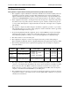
Total Access 900e Series Hardware Installation Guide Physical Description Total Access 916e and Total Access 924e Rear Panel Interfaces Figure 3 shows the Total Access 916e and Total Access 924e products’ rear panel, which contains identical interfaces regardless of the model. T1 0/1 T1 0/3 ETH 0/1 FXO 0/0 VOICE AC INPUT USB GIG 0/1 T1 0/2 T1 0/4 ETH 0/2 CRAFT 10/100/1000 BASE-T BBU Figure 3.
Physical Description Total Access 900e Series Hardware Installation Guide Grounding Point A grounding point is provided to connect the unit to a protective earth ground. Refer to Supplying Power to the Unit on page 25 for connection details. Battery Backup Connection An optional battery backup unit (P/N 1175044L1/L2) is available for use in case of power outages. The battery backup unit connects to the BBU port, which also charges the unit during operation.
Total Access 900e Series Hardware Installation Guide Physical Description LED Descriptions The following table describes LED activity. Table 1. Front Panel LED Descriptions LED STATUS VOICE USB GIG 1 T1 1 through 4 ETH 1/ETH 2 64243916F1-34A Color Indication Off Unit is not receiving power. Green (flashing) On power up, the STATUS LED flashes rapidly for five seconds, during which time the user may escape to boot mode from the CONSOLE port.
Product Specifications 3.
Total Access 900e Series Hardware Installation Guide 4. Unit Installation UNIT INSTALLATION The instructions and guidelines provided in this section cover hardware installation topics such as wall mounting, rack mounting, and installing the unit. Refer to Shipping Contents on page 14 before getting started.
Unit Installation Total Access 900e Series Hardware Installation Guide Mounting Options The Total Access 900e Series may be installed in a wallmount, rackmount, or tabletop configuration.The following sections provide step-by-step instructions for rack mounting and wall mounting.
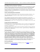
Total Access 900e Series Hardware Installation Guide Unit Installation VOICE VOICE FXO 0/0 GIG 0/1 10/100/1000 BASE-T ETH 0/1 ETH 0/2 T1 0/3 T1 0/4 T1 0/1 T1 0/2 ETH 0/1 ETH 0/2 T1 0/3 T1 0/4 T1 0/1 T1 0/2 FXO 0/0 USB GIG 0/1 10/100/1000 BASE-T CRAFT USB BBU CRAFT AC INPUT BBU AC INPUT Figure 4.
Unit Installation Total Access 900e Series Hardware Installation Guide Follow these steps to safely rackmount the Total Access 900e Series: • • • • • If installed in a closed or multi-unit rack assembly, the operating ambient temperature of the rack environment may be greater than room ambient temperature. Therefore, consideration should be given to installing the equipment in an environment compatible with the maximum ambient temperature specified by the manufacturer.
Total Access 900e Series Hardware Installation Guide Unit Installation The supplemental grounding conductor shall be connected to the equipment using a number 8 ring terminal and should be fastened to the grounding lug provided on the rear panel of the equipment. The ring terminal should be installed using the appropriate crimping tool (AMP P/N 59250 T-EAD Crimping Tool or equivalent).
Battery Backup Unit 5. Total Access 900e Series Hardware Installation Guide BATTERY BACKUP UNIT The ADTRAN battery backup unit (BBU) is an optional device designed as a backup DC power supply for the Total Access 900e Series. Total Access 908e BBU (P/N 1200641L1) The BBU connects to the Total Access 908e through a 2-foot charge/discharge, 2-conductor wire with a keyed modular plug (included with the BBU). The 1200641L1 BBU is a low profile wallmount configuration. The BBU is not rack mountable.
Total Access 900e Series Hardware Installation Guide Battery Backup Unit Batteries are retained and prewired in the BBU in a specific pattern. Battery position is maintained by foam spacers press-fitted against the housing walls. Removing batteries or disconnecting wires compromises correct reassembly and should not be attempted. BBU Safety Notices The BBU should only be used in specified ADTRAN applications. This device complies with Part 15 of the FCC rules.
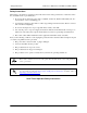
Battery Backup Unit Total Access 900e Series Hardware Installation Guide For a wallmount installation, the BBU installs on heavy plywood (3/4-inch minimum) using two #10 x 3/4-inch pan-head wood screws. Install the BBU as follows: Instructions for Wall Mounting the 1200641L1 BBU Step Action 1 Determine the preferred unit layout to ensure cable plugs reach their designated sockets.
Total Access 900e Series Hardware Installation Guide Battery Backup Unit For a wallmount installation, the BBU installs on heavy plywood (3/4-inch minimum) using four #10 x 3/4-inch pan-head wood screws. Install the BBU as follows: Instructions for Wall Mounting the 1175044L1/L2 BBU Step Action 1 Determine the preferred unit layout to ensure cable plugs reach their designated sockets.
Battery Backup Unit Total Access 900e Series Hardware Installation Guide Specifications Table 2 provides BBU specifications. Table 2. BBU Specifications Battery Part Number: Suppliers: Batteries: Voltage: Backup Time: Wire Gauge: 311212V02 YUASA and Panasonic 7 Ahr per battery -12 VDC per battery Up to 8 hours 18 AWG Environmental Operating Temperatures: Preferred: Charge: -15°C to 50°C Discharge: -20°C to 60°C 20°C Physical Dimensions P/N 1175044L1/L2: Weight: 17-inch W x 6.5-inch H x 3.
APPENDIX A. PIN ASSIGNMENTS The following tables provide the pin assignments for the base unit. Table A-1.
Appendix A Total Access 900e Hardware Installation Guide Table A-2. FXO 0/0 Pinouts Pin Name Description 1, 2 — 3 Ring 4 Tip Tip lead of the 2-wire interface 5, 6 — Unused Unused Ring lead of the 2-wire interface Table A-3.
Total Access 900e Series Hardware Installation Guide Appendix A Table A-5. 1000Base-T Gigabit Ethernet Port Pinouts Pin Name Description 1 TRD0+ Transmit/Receive Positive 2 TRD0- Transmit/Receive Negative 3 TRD1+ Transmit/Receive Positive 4 TRD2+ Transmit/Receive Positive 5 TRD2- Transmit/Receive Negative 6 TRD1- Transmit/Receive Negative 7 TRD3+ Transmit/Receive Positive 8 TRD3- Transmit/Receive Negative Table A-6.
Appendix A 34 Total Access 900e Hardware Installation Guide Copyright © 2013 ADTRAN, Inc.