
Installation guide

Unit Installation Total Access 900e Series Hardware Installation Guide
22 Copyright © 2010 ADTRAN, Inc. 64243916F1-34A
Mounting Options
The Total Access 900e Series may be installed in a wallmount, rackmount, or tabletop configuration.The
following sections provide step-by-step instructions for rack mounting and wall mounting.
Wall Mounting Total Access 900e Series
Follow these steps to safely wallmount the Total Access 900e Series
:
• To avoid damaging the unit, use only the screws included in the shipment when
attaching mounting ears to the chassis.
• When wall mounting the NetVanta, care must be taken not to damage the power cord.
Do not attach the power cord to the building surface or run it through walls, ceilings.
floors, or openings in the building structure.
• The socket-outlet must be installed near the equipment and must be easily accessible.
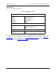
Instructions for Wall Mounting Total Access 900e Series
Step Action
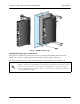
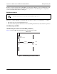
1 Attach the rack mounting brackets rotated 90 degrees so the rackmount tab (two screw holes)
is parallel with the top of the unit (see Figure 4 on page 23)
2 Decide on a location for the Total Access 900e Series. Keep in mind that the unit needs to be
mounted at or below eye level so that the LEDs are visible.
Warning! The Total Access 900e Series can only be wall mounted with the front panel facing to
the right, to the left, or downward (see the example in Figure 4 on page 23). Do not mount
with the LED facing up.
3 Prepare the mounting surface by attaching a board (typically plywood, 3/4-inch to 1-inch thick)
to a wall stud using #6 to #10 (2.5-inch or greater in length) wood screws.
Important! Mounting to a stud ensures stability. Using sheetrock anchors may not provide
sufficient long-term stability.
4 Have an assistant hold the unit in position as you install two #6 to #10 (1-inch or greater in
length) wood screws through the unit’s brackets and into the mounted board (see Figure 4 on
page 23).
5 Proceed to the steps given in Grounding Instructions on page 24.