
User's Manual


TRACER 2 x E1 User’s Manual
61280004L2-1C
Section 1 TRACER Description
6
As a rule, a green LED indicates a normal situation, a red LED indicates an error situation, and a yellow
LED indicates a configuration option. LEDs indicating overall system integrity are listed below.
Self Test .................................... Blinking red if the self-test has completed and failed; Solid red if
self-test is in progress or did not complete
Power ........................................ Green if DC voltage is applied
The LEDs associated with the E1 interfaces are listed below.
CV/CRC .................................... Red if the incoming E1 stream contains code violations, or a CRC
error
LOS/OOF .................................. Red if there is no signal present at the E1 interfaces or if framing
synchronization is lost
Loopback................................... Solid yellow if the E1 interfaces are in local line loopback. Blinking
yellow if the E1 interfaces are in link loopback.
ALM .......................................... Solid red if a UA1 is detected at the incoming E1, blinking red if a
remote alarm signal is found
The functions of the LEDs which relate system configuration information are listed below.
Frequency Plan A...................... Yellow if frequency plan A is selected
Frequency Plan B ...................... Yellow if frequency plan B is selected
Remote Test Active .................. Yellow if the remote test is active
Remote Test Fail ....................... Red if the remote test failed
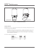
Figure 1-6. BBP Front Panel with Door Closed
ALM
LBK
LOS/OOF
CV/CRC
LOS/OOF
CV/CRC
ALM
LBK
PLAN A
PLAN B
TEST
POWER
RF LOW
LINK DOWN
TRACER
Figure 1-7. BBP Front Panel with Door Open
ALM
LOS
OOF
E1A E1B
LBK
CAS
HDB3 HDB3
AMI AMI
CCS
CAS
CCS
CODE
CV
CRC
TEST
PWR
RESET
A
B
TST
FAIL
RF LOW
LINK
TESTLBKA
ALM
LOS
OOF
GND
CLK
L
Q
RSSI
RF
+5
-5
+12
-12
LBK
CV
CRC
LBKB
5
6
7
8
9
0
1
2
3
4
1234
TX PWR
PWR
PLAN REMOTE ERROR
UP
DOWN