
User's Manual


TRACER 2 X E1 User’s Manual
61280004L2-1C
Section 1 TRACER Description
9
Three SMA connectors, located on the RFC module, provide RF and IF connection points. A test point is
provided for monitoring the received signal strength indicator (RSSI). The voltage (relative to the GND
test point) present on this test point represents the level of the received signal. This signal is used to align
the antenna when installing the system and to verify the link is performing as designed.
NOTE
The voltage level present at the RSSI test point represents a relative signal level of receive strength
from the far end. No direct correlation can be made between RSSI voltage level and actual receive
level in dBm. This test point is provided to assess relative signal level for alignment of antennae.
The only connections that must be made in the field are a coax connection between the baseband
processor and the RFC and a coax connection between the RFC and the antenna. These connections
require male, type N coax connectors.
The IF connector provides the connection between the baseband processor and the rackmounted or
mastmounted RFC. An 8” IF cable (ADTRAN P/N 3125RF027) is provided for rackmount systems.
The TO ANTENNA connection provides the connection between the RFC and the antenna.
CAUTION
When connecting an RF converter (RFC) to a Baseband Processor (BBP), verify that the connector
labeled “IF” on the rear panel of the Baseband Processor is connected via coax to the connector
labeled “IF” on the RF converter. Connecting the Baseband Processor to the incorrect connector on
the RF converter will cause the internal 1 amp 250 V fuse to blow in the Baseband Processor. This
fuse is accessed by removing the top of the Baseband Processor, and is located on the left side of the
chassis when facing the front panel.
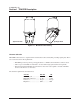
The RFC module is enclosed in either an ETSI-compliant rackmount housing or a weather-tight
enclosure suitable for mastmounting near the antenna for enhanced system performance. The RFC
mastmount and rackmount housings are illustrated in Figures 1-10 and 1-11.
Figure 1-10. Front and Rear of Rackmount RFC Housing
TRACER
IF ANTENNA