
User's Manual


TRACER 2 x E1 User’s Manual
61280004L2-1C
Section 3 Operation
26
MAIN MENU SELECTIONS
System Status Screen
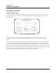
The screen in Figure 3-1 displays the status of major system components. This is a status screen only;
no configurations can be performed. More detailed information can be obtained by way of the Main
Menu (Figure 3-2).
The upper portion of the screen indicates how long the system has been running since the last reset
operation. The “E1A” and “E1B” labels will be highlighted if any error conditions exist on that E1
interface.
The status of the radio link is indicated as Up or Down. The left portion of the screen reports the status
of the local system (the system to which the terminal is attached); the right portion reports the status of
the remote system. The approximate transmitter and receiver signal levels are shown via the bar graphs.
If the link is down and remote end data is unavailable, the bar graphs will show “-” instead of “x.” RFC
Link Up indicates if communications exist on the IF cable connecting the baseband processor to the radio
frequency converter. The Code Sync, Carrier Sync, and E1 Mux Sync will all be “yes” for an
operational link. Chipping code indicates the code to which the system is set.
TRACER SYSTEM STATUS
ELAPSED TIME: 00000 DAYS, 00:00:07
ADTRAN TECHNICAL SUPPORT - 256/963-8716
----- -----
E1A ===| C | / ->>---->>---->>----[ RF UP ]---->>---->>---->>- \ | C |=== E1A
| S |#(- -)#| S |
E1B ===| U | \ -<<----<<----<<----[ RF UP ]----<<----<<----<<- / | U |=== E1B
----- -----
LOCAL TRACER REMOTE TRACER
FREQ PLAN B FREQ PLAN A
SITE: ADTRAN
MIN NOM MIN NOM
[###################_] [###################_]
RX POWER RFC LINK UP: YES RX POWER
CODE SYNC: YES
MIN MAX CARRIER SYNC: YES MIN MAX
[####################] E1 MUX SYNC: YES [####################]
TX POWER CHIPPING CODE: 0 TX POWER
=============================================================================
PRESS ‘M’ - MAIN MENU:
Figure 3-1. System Status Screen