TSU 120 PART NUMBER 1200129L1 USER MANUAL 61200.
901 Explorer Boulevard P.O. Box 140000 Huntsville, AL 35814-4000 Phone: (205) 963-8000 © 1997 ADTRAN, Inc. All rights reserved. Printed in USA.
FCC regulations require that the following information be provided to the customer in this manual: 1. This equipment complies with Part 68 of the FCC rules. The required label is affixed to the bottom of the chassis. 2. An FCC compliant telephone cord and modular plug is provided with this equipment. This equipment is designed to be connected to the telephone network or premises wiring using a compatible modular jack which is Part 68 compliant. See Installation Instructions for details. 3.
Table of Contents AFFIDAVIT REQUIREMENTS FOR CONNECTION TO DIGITAL SERVICES • An affidavit is required to be given to the telephone company whenever digital terminal equipment without encoded analog content and billing protection is used to transmit digital signals containing encoded analog content which are intended for eventual conversion into voiceband analog signals and transmitted on the network.
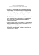
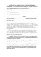
Table of Contents AFFIDAVIT FOR CONNECTION OF CUSTOMER PREMISES EQUIPMENT TO 1.
Table of Contents ( ) A. A training course provided by the manufacturer/grantee of the equipment used to encode analog signals; or ( ) B. A training course provided by the customer or authorized representative, using training materials and instructions provided by the manufacturer/grantee of the equipment used to encode analog signals; or ( ) C. An independent training course (e.g.
Table of Contents Table of Contents Chapter 1. Introduction TSU 120 Overview .............................................................................................. 1 Functional Description ............................................................................... 1 TSU ................................................................................................... 1 TSU 100 ............................................................................................ 2 TSU 120 ...............
Table of Contents Pattern Generation ............................................................................. 20 QRSS Pattern ................................................................................ 20 511 Pattern .................................................................................... 20 Chapter 2. Installation Unpack, Inspect, Power Connection .............................................................. 21 Shipped by ADTRAN ......................................................
Table of Contents Chapter 3. Operation Operation ........................................................................................................... 39 Identification of Front Panel Layout ....................................................... 39 Display Panels .................................................................................... 40 Remote .......................................................................................... 40 DSU/DSX Status ....................................
Table of Contents DS0 Map: A (B) ........................................................................... 49 Port Configuration (Port Config) .............................................. 49 Utility (UTIL) ...................................................................................... 50 Time/Date .................................................................................... 50 Factory Restore ............................................................................ 50 Set Passcode ....
Table of Contents Port Configuration (Port Config) ............................................................ 72 Operation ............................................................................................. 72 0.1 Nx56/64 Port Configuration (Port Config) Menu Items ........ 73 Rate 56/64 .................................................................................... 73 TX CLK ......................................................................................... 73 DATA .................
Table of Contents Run Selftest ................................................................................................. 88 Operation ............................................................................................. 88 Port Tests .................................................................................................... 89 Operation ............................................................................................. 89 Port Test Menu Items for 0.1 Nx56/64 .............
Table of Contents Appendix D. TSU 120 System Messages Alarm Messages .............................................................................................. 120 Network Interface (NI) ........................................................................... 120 Nx56/64 Interface .................................................................................... 120 DSX-1 (PBX) Interface ............................................................................. 121 Status Messages .............
Table of Contents Figure 3-18. Utility Menu Tree ........................................................................ 76 Figure 3-19. Test Menu Tree ............................................................................. 83 Figure 3-20. Pattern Results Display .............................................................. 87 Figure 4-1. Example of Voice and Data Mix ................................................ 91 Figure 4-2. First Two Configuration Menu Items..................................
Chapter 1. Introduction Chapter 1 Introduction TSU 120 OVERVIEW A functional description of the T1 multiplexers, a description of the TSU 120 rear panel, and a summary of the features of the TSU 120 is provided in this section. The unit is shown in Figure 1-1.
Chapter 1. Introduction TSU 100 The TSU 100 is the same as the TSU with the added feature of a slot in the rear panel to house an option module. Each module offers up to four additional data ports. TSU 120 The TSU 120 is the same as the TSU 100 with the addition of a DSX-1 PBX interface to the base of the unit. TSU 600 The TSU 600 is the same as the TSU with the added feature of six slots in the rear panel to house up to six option modules.
Chapter 1. Introduction Identification of Rear Panel Layout The configuration of the rear panel of the TSU 120 is shown in Figure 1-2. 1 2 3 4 5 6 7 OPTION SLOT 1 PORT 0.2 PORT 0.1 DSX-1 EQ IN EQ TR OUT MON POWER V.35 CONTROL/ CHAIN PORT NETWORK NET IN NET RX OUT MON IN OUT 15 14 13 12 11 10 CAUTION: FOR CONTINUED PROTECTION AGAINST RISK OF FIRE, REPLACE ONLY WITH SAME TYPE AND RATNG OF FUSE. .5A/250V 115VAC 60HZ 9 1. Option slot 2. Equipment Input Test Jack 3.
Chapter 1. Introduction 4 DSX-1 Port Connection RJ-45 connector for the DSX-1 port (terminal equipment) V.35 Connection High-speed V.35 digital data interface Power Switch Used to turn power on or off Power Cord Input of permanent power cord Fuse Holder Placement of .
Chapter 1.
Chapter 1. Introduction Interfaces The TSU 120 base unit is equipped with a slot in the rear panel to house option modules which provide a variety of additional data ports. See Figure 1-3. The base unit is equipped with the following five interfaces: • Network DSI interface per AT&T 61402 • DSX-1 (PBX) • Nx56/64 serial V.
Chapter 1. Introduction TSU 120 INTERFACES The Network Interface (NI) port complies with the applicable ANSI and AT&T standards. Network Interface The NI provides the following functions: • AMI or B8ZS coding • Automatic or manual line build out • D4 or ESF framing • Network performance monitoring and reporting • Test loopbacks with QRSS generation and checking • Extensive self test DSX-1 (PBX) Interface The DSX-1 interface provides the following functions: • DSX-1 per ANSI T1.
Chapter 1.
Chapter 1. Introduction OPTION PORTS The option ports vary depending on the option modules installed. Secondary Interfaces (SI) The secondary interface is an additional interface to a DS1, a DSX1 facility, or some other network service, and it offers a source of timing. The type of interface depends on the option module installed. The interface includes the following: • DSX1 An additional DSX-1 interface can be added for data or voice applications.
Chapter 1. Introduction FOUR METHODS OF CONTROL Front Panel The front panel provides complete and easy control of all items that can be configured through menu guided options. The front panel LCD also displays the status of operation and performance reports for the unit. A complete discussion of the operation of the front panel and all the menu options is found in the chapter, Operations. ADTRAN PC Program T-Watch is the ADTRAN PC control program.
Chapter 1. Introduction TSU 120 CLOCK SOURCES The TSU 120 is operable from various clock sources, permitting it to perform properly in many different applications. The network interface clocking options are set by using the clocking options set by using the Network (NI) Configuration menu options.
Chapter 1. Introduction DSX-1 Timed The PBX is the source of timing. The TSU 120 uses the clock derived by the Base DSX-1 interface for transmission timing (see Figure 1-5). The Base DSX-1 source timing is restricted from use when a secondary interface is used at the same time. OSC T1 XMIT (DS1) T1 Receive Network Interface (OPTION) Nx56/64 DSX-1 DTE CLOCK DTE PBX Figure 1-5 DSX-1 Timed Clock Source 12 TSU 120 User Manual 61200.
Chapter 1. Introduction DTE Timed The DTE is the source of timing. The TSU 120 uses the incoming DTE clock to determine the transmission timing. This is typically used in applications where it is necessary to have the DTE as the primary clock source, (such as limited distance line drivers). See Figure 1-6. The DTE source timing is restricted from use when a secondary interface is used at the same time.
Chapter 1. Introduction Internal Timing The TSU 120 is the source of timing. The TSU 120 is configured to use its own internal oscillator as the source of timing. Applications include private line driver circuits where one end is set to network and the other to internal. See Figure 1-7. The internal source timing is restricted from use when a secondary interface is also used.
Chapter 1. Introduction Normal (CSU) Timing The typical timing option arrangement is shown in Figure 1-8. The PBX is looped timed sending data to the TSU 120 which is actually synchronous to the received data. The Network Interface (NI) is the actual source of all timings. This timing option is the same as that typically used for CSUs. This is the preferred mode for use with a PBX application. This timing mode works equally well when the PBX is the source of timing.
Chapter 1. Introduction TSU 120 TESTING The TSU 120 offers three forms of testing: • Self test • Loopback tests (local and remote) • Pattern generation and check Self Tests The self test checks the integrity of the internal operation of the electronic components by performing memory tests and by sending and verifying data test patterns through all internal interfaces.
Chapter 1. Introduction Additionally, the loopbacks can be remotely controlled by out-of-band commands through the T1 ESF FDL or from T-Watch through a modem connection. Classes of Loopbacks There are two classes of loopbacks: network interface and DTE interface. Network Interface Loopbacks Network interface loopbacks (see Figure 1-9) affect the entire T1 data stream. There are two types of network loopbacks, line loopback and payload loopback.
Chapter 1. Introduction DTE loopback loops all data from the DTE back towards the DTE. This loopback occurs just past the interface circuit allowing a verification of the operation of the DTE to TSU 120. This loopback may be initiated by using front panel or T-Watch commands. The DTE (or external test equipment) must provide anytest pattern to check the DTE interface. See Figure 1-10. The TSU 120 also activates a port loopback when the DTE loopback is asserted.
Chapter 1. Introduction TSU 120 Nx56/64 T1 Network Interface (NI) Interface Nx56/64 to Network Control Circuit Port Loopback to DTE Figure 1-11 Port Interface Loopback DSX-1 Interface Loopbacks Line Loopbacks On the DSX-1 interface, the line loopback causes data received at the DSX-1 to be looped back toward the PBX achieving a local loopback. Port Loopback The port loopback is internal and loops all data mapped to the DSX-1 back toward the network interface on the controller.
Chapter 1. Introduction TSU 120 DSX-1 Interface T1 Network Interface (NI) (Controller) DSX-1 PBX PORT LINE LOOPBACKS Figure 1-12 Diagram of Loopbacks Pattern Generation The TSU 120 offers two available test Patterns: QRSS and 511. QRSS Pattern The QRSS pattern is commonly used to simulate real data in T1 interfaces. This pattern can be assigned to appear in all DS0s or only in TST DS0s.
Chapter 2. Installation Chapter 2 Installation UNPACK, INSPECT, POWER CONNECTION Carefully inspect the TSU 120 for any shipping damages. If damage is suspected, file a claim immediately with the carrier and then contact ADTRAN Customer Service. If possible, keep the original shipping container for use in shipping the TSU 120 back for repair or for verification of damage during shipment.
Chapter 2. Installation Power Connection Each TSU 120 unit is equipped with a captive eightfoot power cord, terminated by a three-prong plug which connects to a grounded power receptacle. Power to the TSU 120 must be from a grounded 115 VAC, 60 Hz source. 22 TSU 120 User Manual 61200.
Chapter 2. Installation WARRANTY AND CUSTOMER SERVICE ADTRAN will replace or repair this product within five years from the date of shipment if the product does not meet its published specifications or if it fails while in service. For detailed warranty, repair, and return information refer to the ADTRAN Equipment Warranty and Repair and Return Policy Procedure. Return Material Authorization (RMA) is required prior to returning equipment to ADTRAN.
Chapter 2. Installation GROUNDING INSTRUCTIONS (UL 1459) Grounding instruction information from the Underwriters’ Laboratory UL 1459 Standard for Safety: Telephone Equipment, of September 20, 1993, is provided in this section. An equipment grounding conductor that is not smaller in size than the ungrounded branch-circuit supply conductors is to be installed as part of the circuit that supplies the product or system. Bare, covered, or insulated grounding conductors are acceptable.
Chapter 2. Installation the supplementary equipment grounding conductor is permitted to be made to building steel, to a metal electrical raceway system, or to any grounded item that is permanently and reliably connected to the electrical service equipment ground. Bare, covered, or insulated grounding conductors are acceptable. A covered or insulated grounding conductor shall have a continuous outer finish that is either green, or green with one or more yellow stripes. 61200.
Chapter 2. Installation WIRING Network The rear panel of the TSU 120 has an eight-position modular jack labeled NETWORK. This connector is used for connecting to the network. See Table 2-A for the pinout for the network connector.
Chapter 2. Installation Control In/Chain In This is used as an RS-232 port for connection to a computer or modem (Control In) or to another TSU 120 (Chain In). See Table 2-B for the pinout for the control/chain in connector. Connections The chain in connections are as follows: Connector type RJ-48 Part number AMP# 555164-2 Table 2-B Control In/Chain In Pinout 61200.
Chapter 2. Installation Chain Out This is used to connect to another TSU 120 Chain In connector. See Table 2-C for the pinout for the chain out connector. Connections The chain out connections are as follows: Connector type RJ-48 Part number AMP# 555164-2 Table 2-C Chain Out Pinout PIN NAME 1 GND 2 UNUSED 3 Data transmitted to chained units by the TX DATA TSU 100. Connected to RX DATA of the next unit (Chain in Pin 3). 4 UNUSED 5 Data received from chained units by the RX DATA TSU 100.
Chapter 2. Installation Nx56/64 DTE (V.35) See Table 2-D for the V.35 pinout Nx56/64 DTE pinout. Connections The DTE interface pinout is as follows: Connector type Part number V.35 AMP# 92-4883-3-1 Table 2-D V.
Chapter 2. Installation Base DSX-1 (PBX) The DSX-1 has an RJ-48C connector as defined in Table 2-E. Table 2-E Pinout Connectors for Eight-Position Modular Jack Interface PIN 1 30 NAME DESCRIPTION R1 TXDATA-RING Send data towards the DTE (PBX) 2 T1 TXDATA-TIP Send data towards the DTE (PBX) 3 UNUSED - 4 R RXDATA-RING Receive data from the DTE (PBX) 5 T RXDAT-TIP Receive data from the DTE (PBX) 6,7,8 UNUSED TSU 120 User Manual - 61200.
Chapter 2. Installation POWER UP TESTING AND INITIALIZATION When shipped from the factory, the TSU 120 is set to factory default conditions. At the first application of power, the unit automatically executes a memory self test. A full self test can be run from the front panel, and a pass code and unit ID may be set using the UTIL menu. Self Test Upon a power-up, the LCD displays Memory Test Now Testing and the Test LEDs are illuminated.
Chapter 2. Installation Set User Passcode The TSU 120 is designed to operate with or without the use of a passcode. The passcode should be a number easily remembered. Once entered, the passcode is required to access any operation other than viewing. To Establish a Passcode Select Set Passcode (item 3) under the UTIL menu. At the New Passcode prompt, use numbers from the front panel of the keyboard to enter a unique number up to four digits. After pressing Enter a verification prompt is displayed.
Chapter 2. Installation No Passcode Desired At the new New Passcode prompt (in the Set Passcode menu), press Enter without any numerical entry. The system nullifies the need to enter a passcode for subsequent use and proceeds to the Unit ID prompt. 61200.
Chapter 2. Installation Set Unit Identification Number The Unit ID sets the unit to respond to remote control (controlled by a device other than the front panel). If no Unit ID is recorded it is not possible to operate from any remote control device, including the local PC. To Set the Unit Identification In the Unit ID menu (item 4) under the UTIL menu, enter any value between 2 and 250. The number 1 is reserved for the PC.
Chapter 2. Installation Set Control Port The TSU can be configured from the control port only when a unit ID number has been entered. (It can be configured from the faceplate whether a unit ID number has been entered or not.) If the control port is to be used, the control port baud rate must also be selected. Possible uses of the control port are control in and chain in. Control In (PC) The unit can be controlled from an external PC connected directly or through a modem to the Control In port.
Chapter 2. Installation PC or Modem Control Input Chain Output TSU 120 Chain In Chain Output TSU 120 Chain In Chain Output TSU 120 Figure 2-1 Example of Chain In At this point, the Unit Initialization procedure is concluded. If the unit is to be configured remotely, there are no additional items necessary to complete prior to executing remote configuration. The Passcode, the Unit ID, and the Control Port settings are stored in a nonvolatile memory.
Chapter 2. Installation Normal Power-Up Procedure After the unit has been put into operation with the initial power-up and initialization, the subsequent power-up procedure includes only the Power-Up Self Test followed by the request for a Passcode (password) if this option was selected during initialization. Use the number keys to enter the previously recorded passcode followed by pressing Enter.
Chapter 2. Installation 38 TSU 120 User Manual 61200.
Chapter 3. Operation Chapter 3 Operation OPERATION The TSU 120 can be configured and controlled by two different methods: by front panel operation or by the optional control software called T-Watch. Identification of Front Panel Layout The TSU 120 front panel is used to both monitor operation and control the configuration of the unit. The display panels and operation keys on the TSU 120 front panel are identified in Figure 3-1.
Chapter 3. Operation The display panels and operation keys called out in Figure 3-1 are described in the sections that follow. Display Panels Remote When illuminated, this panel indicates that the TSU 120 is accessed remotely by the PC program. DSU/DSX Status The TSU 120 basic unit is equipped with an Nx56/64 serial interface port and a DSX-1 (PBX) interface. The DSU/DSX status LEDs display the operational condition of these two base ports.
Chapter 3. Operation CSU Status Indicates the status of the network interface located in the unit base. These LEDs show the same indication as the DSU and Module, with the addition of the Error LED. The Error LED indicates an error such as BPV, XSOs, or CRC error. Operation Keys Copy Used in the DS0 mapping menu operations to copy the last data entered into the current DS0. This key operates without pressing the Shift key. Remote Reserved for future use.
Chapter 3. Operation Enter Activates menu selections. Enters data value selections into the system. Up and Down Arrows Moves cursor through the menus or scrolls through data selector lists. Keypad These nine keys have dual functions. The first function is indicated by the lettering on the key itself. This is a standard phone keypad. The second function is a shifted function accessed by pressing and holding shift key + # along with another key.
Chapter 3. Operation General Menu Operation The TSU 120 uses a multilevel menu structure containing both menu items and data fields. All menu operations and data are displayed in the LCD window. The menu items are numbered and can be viewed by scrolling with the Up and Down Arrows. • Data Field A menu item followed by a colon (:) identifies a data field that can be edited.
Chapter 3. Operation Figure 3-2 Select a Menu Item The unit responds by displaying the first two menu items (in this example, on the Configuration menu), with the cursor on the first menu item. An Up or Down Arrow shown in the lower right corner of the LCD indicates additional menu options in that direction. See Figure 3-3. Figure 3-3 Sample Menu Set the Data Field Data fields preceded by a colon (:) can be edited. See Figure 3-4. With the cursor positioned on the menu item number, press Enter.
Chapter 3. Operation that value. When the value is set, the cursor moves back to the menu item position indicating the operation is complete. Another menu field may be selected, or press Cancel to return to the menu. Pressing Cancel prior to pressing Enter voids any data changes. The original data value is restored and the cursor returns to the menu field. Display Only Data Fields Data fields preceded by an equal (=) symbol cannot be edited. See Figure 3-4.
Chapter 3. Operation Data Port Identification When configuring the unit, menu selections will sometimes include options from data port menus. Selection of data ports is necessary because the TSU 120 uses a Slot.Port method to identify which data port the menu item is referencing. For example, the base unit is slot zero (0). Anything in the option slot is referenced as Slot 1.
Chapter 3. Operation MENU STRUCTURE The TSU 120 uses a form of hierarchical menus to access all features. The topmost or Main menu level (see Figure 3-5) leads to submenus which are grouped by functionality. All menu operations are displayed in the LCD window as illustrated in Figure 3-6. The menu structure diagram, shown in Figure 3-5, is a limited overview. A detailed description of each menu item, presented in menu order, immediately follows.
Chapter 3. Operation The opening menu display as seen in Figure 3-6 is the access point to all other operations. There are four main menu items: Status, Configuration, Utility, and Test. Each Main menu item has several functions and submenus to identify and access specific parameters. In the discussions that follow, each Main menu contains a complete menu diagram to identify the location of each operation.
Chapter 3. Operation View History This menu item displays date and time history of up to 20 status changes of the unit. Port Status Port Status is used for viewing the signals being monitored on the data ports. Remote Port Shows status of incoming commands on the chain in port. Configuration (CONFIG) The Configuration menu is used to set the TSU 120 operational configuration.
Chapter 3. Operation Utility (UTIL) The Utility menu is used to view and to set system parameters. This menu includes the following items: Time/Date Displays and can be used to set the time and date. Factory Restore Restores the factory default settings to all unit parameters. See the appendix, System Configuration Chart, for defaults. Set Passcode Allows a passcode to be added, changed, or deleted. Unit ID Displays and can be used to set the unit ID.
Chapter 3. Operation Test The execution of tests will disrupt some normal operations. See individual menu items concerning tests before executing any. The Test menu is used to initiate different types of tests of the unit and to view test results. Test results are displayed in the LCD window. The menu contains the following items: Network Tests Network Tests control the activation of loopbacks and the initiation of data test patterns. Run Self Test Run Self Test executes a full internal self test.
Chapter 3. Operation DETAILED MENU OPERATION Status The Status menu branch provides the ability to view the status of the TSU 120 operation. See Figure 3-7. % AS %EF 1) NI PERF RPTS 2) NI ERRORS ES SES UAS (ALARM LIST) 3) ACTIVE ALARMS END OF LIST 1) STATUS 4) VIEW HISTORY (HISTORY LIST) END OF HISTORY 1) DTE DATA 5) PORT STATUS 6) REMOTE PORT 2) DTE STATUS 0.1 NX56/64 0.2 DSX-1 3) PORT RATE DSX-1 ERRORS (OPTION PORTS) Figure 3-7 Status Menu Tree Menu flow is normally depicted from left to right.
Chapter 3. Operation Network Performance Reports (NI PERF RPTS) The Network Interface Performance Reports display the user copy of the performance data. The TSU 120 maintains this performance data on the network in compliance with ANSI T1.403 and AT&T document TR54016. The data displayed is data accumulated over the last 15 minutes and over the last 24 hours. This data is available only when configured for the ESF network format.
Chapter 3. Operation ES SES UAS: number of errored seconds (one or more errors per second) number of severely errored seconds (more than 320 errors per second) number of unavailable seconds (10 or more consecutive seconds) If insufficient time has passed to collect data or the network format is configured as D4, NA is displayed. Continue with standard operating procedures to exit the display. When this menu is active, performance data can be cleared by pressing Clear (shift + 9) on the keypad.
Chapter 3. Operation Network Interface Errors (NI ERRORS) The NI Errors menu is used to view the type of errors detected by the Network Interface (NI). A blinking CSU error LED indicates that network errors are detected. With the cursor on Main menu item 1)STATUS, activate the menu with Enter or number 1. The unit displays the first two Status menu items with the cursor on 1)NI PERF RPTS. With the arrows or number 2, select 2)NI ERRORS. Activate the selection with Enter or number 2.
Chapter 3. Operation Active Alarms This menu item displays a list of current alarms reported by either the base controller or any of the ports. If no alarms are current, using this menu item displays No Active Alarms. This display includes two lines of text. The top line is the alarm source. The bottom line is the alarm message. A list of alarm messages is found in the appendix, TSU 120 System Messages. With the cursor on Main menu item 1)STATUS, activate the menu with Enter or number 1.
Chapter 3. Operation which was viewed when Alarm (shift + 8) was initiated. View History This menu item is used to both view and clear the accumulated status changes of the unit. View History displays a history of 20 status changes in the unit, including the date, time, and type of change. The unit also records for viewing the date and time an alarm became active and when it became inactive, as well as the date and time of test activation and deactivation.
Chapter 3. Operation Port Status Port Status is used to view the signals monitored on the data ports. For example, the Nx56/64 interface monitors the RTS, CTS, TD, and RD, along with other signal lines. When a port is selected, the LCD indicates if the signal is present. With the cursor on Main menu item 1)STATUS, activate the menu with Enter or number 1. The unit displays the first two Status menu items with the cursor on 1)NI PERF RPTS. With the Arrows or number 5, select 5)PORT STATUS.
Chapter 3. Operation DTE Status An asterisk (*) indicates an active status of the following lines: RTS CTS DCD DSR Request To Send from DTE Clear To Send to DTE Data Carrier Detect to DTE Data Set Ready to DTE Port Rate The Port Rate displays the current setting of the Nx port. Continue with standard operating procedures to exit the displays. 0.2 DSX-1 Menu Items: DSX-1 Errors CRC As asterisk is displayed under the CRC if there are CRC errors in extended superframe format (ESF) mode.
Chapter 3. Operation With the cursor on Main menu item 1)STATUS, activate the menu with Enter or number 1. The unit displays the first two status menu items with the censor on 1). With the Arrows or number 6, select 6)REMOTE PORT. Activate the selection with Enter or number 6.
Chapter 3. Operation Configuration (CONFIG) The Configuration menu is used to set the TSU 120 operational configuration, including all network interface parameters and the allocation of the DS0s and the port parameters. See Figure 3-11.
Chapter 3. Operation Menu flow is normally depicted from left to right. Arrows on the lower right of the screen indicate the direction of scrolling to use to view additional menu items. At every level of the menu pressing Cancel returns the system to the previous menu level. Pressing Cancel repeatedly returns the system to the Main menu. Network (NI) This menu item accesses the configuration of parameters associated with the network interface in the base unit.
Chapter 3. Operation YEL ALARM Enables and disables the transmitting of yellow alarms. Choices: ENA, DISA XMIT PRM Enables and disables the sending of PRM data on the facility data link (FDL). The PRM data continues to be collected even if XMIT PRM is disabled (possible only with ESF Format). Choices: Off, On TIMING MODE Selects the clock source for transmission toward the network from the NI.
Chapter 3. Operation Unit The Unit menu is used to change the baud rate of the Control In port and the setup of the Dial Out port. Operation Follow standard operating procedure to access the Unit menu. With the cursor on 2)UNIT, activate the menu with Enter or number 2. The unit displays the first two menu items. Continue with standard operating procedure to select the baud rate, set modem flow control, set up the number used for alarm dial out, and exit the menu.
Chapter 3. Operation Map Exchange (Map Xchng) The Map Exchange menu is used to enable and set the automatic time-of-day map switch. The unit provides selection of the hour, minute, and seconds for the map switching to take place. Operation Follow standard operating procedures to access the Auto Map Changing menu item. With the cursor on 3)MAP XCHNG, press Enter. The cursor moves to the select position over Auto or Off, whichever is displayed or currently active. See Figure 3-12.
Chapter 3. Operation @ @ Figure 3-13 Selection Times for Map Exchange With the cursor on 1)Map A, press Enter to activate the selection fields for hour and minute. The cursor first moves to the hour position. Type in numbers and press Enter. The selected hour is entered and the cursor moves to the minute position. Set minutes by the same method as used to set the hours; seconds are defaulted to zero (0). If a number is mistakenly entered, pressing Cancel interrupts the editing process.
Chapter 3. Operation Map In Use This menu item is used to control the DS0 map used by the TSU 120 and to display the map in current use. Operation Follow standard operating procedure to access the Map In Use menu item. Notice the current Map In Use is displayed. If no change is desired, proceed to another menu selection. To manually change the Map In Use, place the cursor on the menu selection 4)MAP IN USE and press Enter. The cursor moves to the select position over A or B. Scroll to select A or B.
Chapter 3. Operation DS0 Map A and DS0 Map B The DS0 maps designate which DS0s are assigned to which port. See Figure 3-14. There are three maps, DS0 Map A, DS0 Map B, and the Temporary (Temp) map. TEMP DS0 A DS0 B Figure 3-14 DS0 Map Designations DS0 A and DS0 B are the current maps used by the TSU 120. The Temp map is used to generate a map before putting it into use. DS0 A can be copied to DS0 B by copying the DS0 A map into the TEMP map and then applying (writing) the TEMP into DS0 B.
Chapter 3. Operation CREATE TEMP This creates a map by defining a port or Idle for all DS0s. Any or all of the DS0s can also be designated for Passthru if a secondary interface capable of Passthru is present. When 2)CREATE TEMP is selected, all DS0s are set to Idle, and those in use are set to the proper port. A sample selection follows: DS0: 01 to 24 PASSTHRU: Y for Yes N for No PORT: IDLE, TST, 0.
Chapter 3. Operation Scroll to select the port which is dependent on the installed option card. Press Enter to complete the selection and move the cursor to the next field, DS0. With the cursor on the DS0 field, the DS0 number can be incremented or decremented by scrolling. If Copy is pressed, the contents of the last DS0 entered are placed in the new DS0 number. When all entries are complete, Cancel moves the cursor to the last of the menu choices, 6)APPLY.
Chapter 3. Operation REVIEW TEMP This menu item is operated the same for the TEMP map as is 3)REVIEW MAP A or MAP B. EDIT TEMP The map in the TEMP file can be edited to whatever configuration is desired. If Map A had been copied into the TEMP file, then after editing, the TEMP file could be applied to MAP A or MAP B. With the cursor on 5)EDIT TEMP, press Enter to display the selection screen with the cursor on the first DS0 number.
Chapter 3. Operation When the desired selection is displayed, press Enter to activate the selection, followed by Cancel to return to menu operation. Port Configuration (Port Config) Port Configuration is used to select and configure the parameters associated with any data port in the unit. For example, parameters for the DSX-1 (PBX) interface are set through this menu. The items that can be set depend on which option module is installed. The Base Nx port is always present.
Chapter 3. Operation Scroll to display the data port to be configured and press Enter to select. The unit displays the first of six menu items for the Nx56/64. 0.1 Nx56/64 Port Configuration (Port Config) Menu Items The menu items are: RATE 56/64 This sets the base rate of the interface. The actual data rate depends on the number of DS0s assigned to the Nx port. The DTE data rate vs. the number of DS0s is provided in the appendix, DTE Data Rate Chart.
Chapter 3. Operation DCD Data Carrier Detect. Indicates to the DTE when a valid signal is being received at the Network Interface. Choices: Normal (see Table 3-A) or Force On DSR Data Set Ready. This signal indicates to the DTE when the DCE is turned on and ready for operations. Choices: Normal (see Table 3-A) or Force On 0 INHIB The Nx interface will detect an uninterrupted string of zeros (0s) being transmitted toward the network, and if 0s are transmitted for >1 second, the TSU 120 will force 1s.
Chapter 3. Operation 0.2 DSX-1 Port Configuration (Port Config) Menu Items The menu items are: Format Format sets the frame format for the base DSX-1 interface. Choices: D4, ESF Code Code sets the line code for the base DSX-1 interface. Choices: AMI B8ZS Yellow Alarm YEL Alarm enables and disables the transmitting of yellow alarms. Choices: ENA, DISA Line Length (ft) Line Length provides selection of the proper output level for the base DSX-1 based on the length of the interface cable.
Chapter 3. Operation UTILITY (UTIL) The utility menu tree is used to view and to set system parameters (see Figure 3-18). This includes setting the time and date and resetting all parameters to factory values or to re-initiate the unit. This menu is also used to view the unit software revision and the unit ID setting.
Chapter 3. Operation Time/Date This menu option is used to view or to edit the current time and date. The time and date are maintained during power off conditions. Operation Follow standard operating procedure to access the 3)UTIL menu items. With the cursor on 1)TIME/DATE, activate the menu with Enter or number 1. The unit displays the current time and date with the cursor on the T in Time. Use Enter to move to the first entry position and numbers to set the desired hour and minutes.
Chapter 3. Operation Factory Restore This menu item is used to restore the factory default setting for all unit parameters. It will restore all parameters, including configured DS0 maps, to the factory settings. Factory defaults are listed in the appendix, System Configuration Charts. Operation Follow standard operating procedure to access the 3)UTIL menu items. With the cursor on 3) FACTORY RESTORE, press Enter.
Chapter 3. Operation Set Passcode Enter Passcode from Other Menus The appearance of the Passcode prompt may make an unexpected appearance from other menu operations. This happens only when the unit is operating in the limited access mode, i.e., without an active passcode. The limited access mode may become active even if a passcode was entered as it does when there is no activity for ten minutes.
Chapter 3. Operation Unit ID: ID This menu is used to access the current Unit ID setting. Viewing is available in limited access mode. Editing or changing the Unit ID requires the use of a password as in editing mode. Unit Identification numbers must be between 2 and 250. If an out of range number is entered, the unit assumes the upper limit number of 250. Operation Follow standard operating procedures to access the 3)UTIL menu items.
Chapter 3. Operation Software Revision (Software Rev) This menu provides access to the display of the current software revision level loaded into the base unit controller. This information is required when requesting assistance from ADTRAN Customer Service or when updates are needed. Operation Follow standard operating procedures to access the 3)UTIL menu items. With the cursor on 6)SOFTWARE REV, press Enter to display the current software revision level. Use Cancel to exit. 61200.
Chapter 3. Operation Port Utility This menu provides access to the display of the current software information for each port installed in the unit. This information is required when requesting assistance from ADTRAN customer service or when updates are needed. Operation Follow standard operating procedures to access the 3)UTIL menu items. With the cursor on 7)PORT, press Enter to display the first available port. Scroll through the available ports to display the desired port name.
Chapter 3. Operation TEST The Test menu is used to initiate different types of tests of the unit and to view test results. Test results are displayed in the LCD window. The Test menu contains four items (see Figure 3-19). The execution of tests will disrupt some of the normal operation. See individual menu items concerning tests before executing.
Chapter 3. Operation Network Tests Network tests are used to control the activation of loopbacks and the initiation of data test patterns. See Figure 3-5 for the list of tests. Network tests are run on the Network Interface (NI). Three different test configurations can be selected to determine the type of loopback and the pattern to run. Test results are displayed in the LCD window. The execution of Network Tests will disrupt normal data flow unless only TST DS0s are selected for testing.
Chapter 3. Operation REMOTE LOOPBCK This activates the same loopbacks as Local Loopback but at the far end. It uses either the in-band loop-up code as specified by ANSI T1.403 for line loopback (ATT In-Band LLB), or the FDL as specified in ANSI T1.403 for payload and line loopback codes.
Chapter 3. Operation PATTERN This sets the pattern for the test and initiates the transmission of the pattern. The test is terminated by selecting None. The following patterns are available: QRSS All DS0s QRSS TST DS0s None Generates a QRSS test pattern and inserts the pattern into all DS0s Inserts a QRSS pattern in those DS0s mapped as TST in the currently active map (A or B) Terminates pattern generation QRSS always runs at 64K/DS0. Use the up and down scroll to select, for example, QRSS ALL DS0.
Chapter 3. Operation * Figure 3-20 Pattern Results Display ES SES SES *SYNC The number of errored seconds with one or more errors per second. The number of severely errored seconds with more than 320 errors per second. The number of seconds with more than 320 bit errors Indicates if pattern sync is, (yes) or is not, (no) valid. The asterisk (*) indicates if pattern sync has been lost since the start of testing. Results can be cleared by pressing Clear (shift + 9).
Chapter 3. Operation Run Selftest This menu selection is used to execute a full internal self test. The results of the self tests are displayed in the LCD. Upon invoking the command the LCD displays System Self-Test and the Test LEDs are illuminated. Test failures are displayed in the LCD window. The self test consists of the following steps: 1. Board level tests. Each of the TSU 120 boards contain an on-board processor which executes a series of tests checking the circuitry on the board. a.
Chapter 3. Operation Port Tests The Port Tests menu is used to activate testing of specific data ports. It controls the activation of loopbacks and the initiation of data test patterns. Test results are displayed in the LCD window. The execution of Port Tests will disrupt normal data flow in the port being tested. Operation Follow standard operating procedures to access the 4)TEST menu item. With the cursor on 3)PORT TESTS, press Enter or number 3. The unit displays the available ports.
Chapter 3. Operation 511 PATT Activates the generation of the 511 test pattern. The pattern check circuitry is enabled and a test started. The test is ended by selecting OFF. The pattern generation and check is disabled. ON OFF DIS 511 RESLT Displays the results of the 511 test indicated in the 511 option. The results are in the form of the number of errored seconds. The error count can be cleared by pressing the Clear key (shift+9). Port Test Menu Items for 0.
Chapter 4. Example Operations Chapter 4 Example Operations This chapter provides examples of how to configure the system for a variety of operations. VOICE AND DATA MIX The following is an example of the use of a TSU 120 to mix voice data from a PBX with data from a customer’s DTE, possibly a LAN bridge (see Figure 41). This example assumes that B8ZS service is not available end- to-end and therefore must use 56K (672K rate) for the data and run AMI on the network.
Chapter 4. Example Operations STEPS TO SET UP VOICE AND DATA MIX The five steps required to set up voice and data mix are presented in this section along with tables that provide examples of the required information. Prior to Step 1 Complete the configuration chart. The configuration charts from the appendix, System Configuration Charts, can be copied and filled out to use as a reference or guide prior to actually setting any configuration. Step 1.
Chapter 4. Example Operations Step 2. Configure DTE Port: (0.1 Nx56/64) Table 4-B provides configuration information for DTE ports. Table 4-B Configuration for DTE Port MENU ITEM 1)RATE 56/64 2)TX CLK CNTRL 3)DATA SELECTION USED 56K INTERNAL NORM SELECTIONS AVAILABLE 56K, 64K INTERNAL, INTERNAL & INVERTED, EXTERNAL NORMAL, INVERT 4)CTS FORCED ON NORMAL, FORCE ON 5)DCD FORCED ON NORMAL, FORCE ON 6)DSR FORCED ON NORMAL, FORCE ON 7) "0" INHIB ON ON, OFF 8) INBAND OFF ON, OFF Step 3.
Chapter 4. Example Operations Step 4: Complete the DS0 Map Configuration Table 4-C provides information for configuring DS0 maps. Table 4-C Configuration for DS0 Map DSO # ASSIGN TO PASSTHRU DSO # ASSIGN TO PASSTHRU 1 0.2 DSX-1 NO 13 0.1 Nx56/64 NO 2 0.2 DSX-1 NO 14 0.1 Nx56/64 NO 3 0.2 DSX-1 NO 15 0.1 Nx56/64 NO 4 0.2 DSX-1 NO 16 0.1 Nx56/64 NO 5 0.2 DSX-1 NO 17 0.1 Nx56/64 NO 6 0.2 DSX-1 NO 18 0.1 Nx56/64 NO 7 0.2 DSX-1 NO 19 0.1 Nx56/64 NO 8 0.
Chapter 4. Example Operations Step 5: Complete a Configuration Table for the Base DSX-1 Port Table 4-D provides information for configuring the DSX-1 (PBX) interface. Table 4-D Configuration for DSX-1 PBX Passthru MENU ITEM SELECTION USED SELECTIONS AVAILABLE 1)FORMAT D4 D4, ESF 2)CODE AMI AMI, B8ZS 3)YEL ALARM ENA ENA, DIS 4)LINE LENGTH 5)INBAND LOOPBACK 6)ROB BIT SIG Step 6: 400Ft.
Chapter 4. Example Operations CONFIGURING THE NETWORK INTERFACE Place the cursor on 1)NETWORK (NI) with the number 1 or by scrolling. Activate the Network Interface Configuration menu with Enter or the number 1 again. The unit displays the first two Network (NI) menu items (see Figure 4-3). (AMI) Figure 4-3 First Two Network (NI) Configuration Menu Items The Code (Item 2) is incorrectly set. To make changes, scroll down or use number 2 to select the CODE menu item.
Chapter 4. Example Operations Figure 4-4 First Two Network (NI) Menu Items 61200.
Chapter 4. Example Operations CONFIGURING THE DS0 MAP From the first menu position scroll down or use number 5 to select the DS0 MAP A configuration. Press number 5 again or Enter to enter the DS0 MAP A Configuration menu (see Figure 4-5). Figure 4-5 DS0 Map A and Map B Configuration Menu Items Scroll down or press number 2 to place the cursor on 2)CREATE TEMP menu item. Press Enter to activate the Create Map menu which opens a display from which a DS0 number can be selected (see Figure 4-6).
Chapter 4. Example Operations Scroll down to advance through the Port list until the 0.2 DSX-1 Port name is displayed (see Figure 4-7). Press Enter to select and move the cursor back to the DS0 # field. Figure 4-7 Display of DS0 Port Name Another DS0 may be selected by incrementing the DS0 number using the Up Arrow key or, for this example, typing number 2. Since the data for this DS0 is identical to the previous DS0 just entered, it can be duplicated using Copy.
Chapter 4. Example Operations TEMPORARY MAP The TSU 120 is now holding the newly created DS0 Map A in a file as a temporary map. It can be reviewed or edited through the DS0 Map A menu. Review To Review the Temporary file, follow standard operating procedures to access the first two menu items of 5)DS0 MAP A (see Figure 4-8). Figure 4-8 First Screen for Choosing to Review Temporary Files Throughout this review example, it is assumed that DS0 17 was inadvertently skipped.
Chapter 4. Example Operations Edit The Review reflects that one of the DS0s is still programmed as Idle, and since the 0.1 Nx56/64 port has one less DS0, the error must be somewhere between DS0 13 and 24. The map that was just created is still a Temp Map, and must be edited as such. Return to the DS0 MAP A configuration items by using Cancel. Use number 5 or scroll down to move the cursor to 5)EDIT TEMP (see Figure 4-10). Press Enter to display the settings for DS0 #1 that have just been entered.
Chapter 4. Example Operations Figure 4-11 Window Showing the Error To correct the setting press Enter twice to advance the cursor to the Port data field. Use scrolling to display the correct Port and Enter to record the selection. The Temporary Map can be reviewed as many times as necessary. When all corrections are completed use Cancel to exit the Edit Temp menu. The unit returns to the DS0 Map A menu listing with the cursor on 6)APPLY TEMP >A. Press Enter to activate Apply.
Chapter 4. Example Operations Scroll to select Yes, and press Enter to confirm Apply. The unit displays Map Applied as the map just created is written into Map A and will be used to pass data. The entire map can be cleared by first selecting CREATE, which has all DS0s set to PSTRU=N and PORT=IDLE, and then select APPLY to write the Idle map into the Current map. Use Cancel to exit DS0 Map A and return to the Config menu.
Chapter 4. Example Operations Using the same operational methods as before, select item 2)RATE to change from 64K mode to 56K mode. Scroll to continue viewing the remainder of the menu selections, comparing all the settings against the configuration chart. Cancel returns to the PORT menu. Scroll to change the port designation to 0.2 DSX-1. Enter the DSX-1 Configuration menu. The TSU 120 is now completely configured and capable of passing data from the PBX and the DTE.
Chapter 4. Example Operations TESTING EXAMPLE If the example operations in the preceding pages were followed, the TSU 120 is completely configured and capable of passing data from the PBX and the DTE. Prior to actually using the configuration to pass voice and data, it is recommended to run tests on the circuit. Testing consists of sending a test pattern from end-to-end and checking for errors in the pattern. There are two types of tests used to accomplish this.
Chapter 4. Example Operations Figure 4-15 Test Menu One The unit begins a display of the menu items. The selections available for each of the four screens (see Figure 4-16) are selected by scrolling. 106 TSU 120 User Manual 61200.
Chapter 4. Example Operations LINE ON PAYLOAD ON NO LOOPBACK ATT Inband LLB ANSI FDL LLB AVSI FDL PLB NO LOOPBACK QRSS ALL DS0s QRSS TST DS0s NO NONE NO TEST PATTERN NO TEST DS0s ES BES SES SYNC Figure 4-16 The Four Test Menu Windows 61200.
Chapter 4. Example Operations With the cursor on 1)REMOTELOOPBK, Enter activates the menu. Scroll to select a setting for PAYLOAD in the data field. When selected, press Enter to activate. This initiates the transmission of a loop-up code toward the far end (see Figure 4-17). Figure 4-17 Screen that Appears During Loopback Verification The TSU 120 verifies that the far end has gone into loopback by verifying the receipt of the code at the originating end.
Chapter 4. Example Operations The TSU 120 begins to automatically check for synchronization and bit errors. The results of this check are shown under menu item 4)PATTERN RESULTS (see Figure 19). * Figure 4-19 Window Displaying Test Pattern Results The Test Pattern Results are explained in the following discussion : The number of errored seconds with one or more errors per second. The number of severely errored seconds with more than 320 errors per second.
Chapter 4. Example Operations Test the Nx56/64 Interface The Nx56/64 interface is tested by essentially the same method as the Remote Loopback is tested. From the 4)TEST Main menu scroll or use number 3 to select 3)PORT TEST. Enter activates the PORT TEST menu. Scroll to select the Port to test and Enter to activate. (For this example the 0.1 Nx56/64 is used.) The unit displays a menu with the cursor on 1)LOOPBK. Scroll to select Remote and Enter to activate. The display shows Looping while sending a V.
Appendix A. TSU 120 Menu Tree Appendix A TSU 120 Menu Tree This Appendix contains the complete menu tree for the TSU 120. 61200.
Appendix A. TSU 120 Menu Tree % AS %EF 1) NI PERF RPTS ES SES 2) NI ERRORS 1) STATUS UAS (ALARM LIST) 3) ACTIVE ALARMS END OF LIST (HISTORY LIST) 4) VIEW HISTORY 1) FORMAT END OF HISTORY 0.1 Nx56/64 5) PORT STATUS 0.
Appendix B. DTE Data Rate Table Appendix B DTE Data Rate Table This chapter contains the DTE data rate chart. 61200.
Appendix B. DTE Data Rate Table Table B-A DTE Data Rate Vs.
Appendix C. System Configuration Charts Appendix C System Configurations Chart This appendix contains tables to support the chapter, Example Operations. Five steps/tables are provided to aid in configuring the system. Step 1: Configure Network.
Appendix C. System Configuration Charts Step 2: Configure DTE PORT: (0.1 Nx56/64). Table C-B Configuration Chart for DTE Port MENU ITEM SELECTION USED SELECTIONS AVAILABLE 1)RATE 56/64 56K, 64K* 2)TX CLK CNTRL INTERNAL*, INTERNAL & INVERTED, EXTERNAL 3)DATA NORMAL*, INVERT 4)CTS NORMAL*, FORCE ON 5)DCD NORMAL*, FORCE ON 6)DSR NORMAL*, FORCE ON 7)"0" INHIB ON, OFF* 8)INBAND ON, OFF* *=Factory Default Step 3: Select number of DS0s/PORT.
Appendix C. System Configuration Charts Step 4: DS0 Map A Configuration. Table C-C DS0 Map A Configuration DSO # ASSIGN TO PASSTHRU? DSO # 1 13 2 14 3 15 4 16 5 17 6 18 7 19 8 20 9 21 10 22 11 23 12 24 ASSIGN TO PASSTHRU? Step 5: DS0 Map B Configuration. Table C-D DS0 Map B Configuration DSO # ASSIGN TO PASSTHRU? DSO # 1 13 2 14 3 15 4 16 5 17 6 18 7 19 8 20 9 21 10 22 11 23 12 24 61200.
Appendix C. System Configuration Charts 118 TSU 120 User Manual 61200.
Appendix D. TSU 120 System Messages Appendix D TSU 120 System Messages This appendix lists and defines the alarm and status messages that appear on the TSU screen. 61200.
Appendix D.
Appendix D. TSU 120 System Messages DSX-1 (PBX) Interface The following messages indicate the status of the DSX1 (PBX) interface: Frame Slip Indicates a Frame Slip has occurred on the DSX-1 interface; this is present in Alarm History only Line Loop Up Line loopback activated 61200.
Appendix D.
Appendix D. TSU 120 System Messages DSX-1 (PBX) Interface The following messages indicate the status of the DSX1 (PBX) interface: Frame Slip Indicates a Frame Slip has occurred on the DSX-1 interface; this is present in Alarm History only Line Loop Up Line loopback activated 61200.
Appendix D. TSU 120 System Messages 124 TSU 120 User Manual 61200.
Index Index Symbols 0.1 Nx56/64 58, 73, 87, 89, 93, 99, 101, 110 0.1 Nx56/64 Port 73 0.
Index DSX-1 40, 59, 75, 90, 95, 99, 104 DSX-1 errors 59 DSX-1 interface 75, 121, 123 DTE interface loopback 17, 18 DTE loopback 17, 18 DTE status 59 DTE timed 11, 13 F factory restore 50, 73, 78, 122 far end looped back test 105 FIFO alarm 120 fractional T1 85, 87 frame slip 123 front panel 5, 10, 16, 18, 31, 32, 34, 35, 39, 88 front view 1 FT1 1 full drop and insert 5, 6, 9 FXS 6 G grounding instructions 24 H history 40, 49, 57 I in-band loopback 75 installation 21 interface loopback 17, 18, 19 interf
Index 1, 5, 6, 7, 9, 16, 17, 29, 40, 46, 58, 72, 74, 87, 93, 110 Nx56/64 serial interface 7, 9, 16, 17, 40 O OCU DP 6, 9, 46 operation 5, 8, 10, 16, 18, 32, 34, 37, 39, 40, 41, 43, 45, 47, 48, 51, 52, 56, 58, 61, 66, 68, 70, 71, 72, 74, 77, 78, 79, 83, 88, 89, 91, 99, 104, 105, C-115 operation keys 39, 40, 41 option module 2, 5, 6, 9, 72, 90 option port 9, 72 P passcode 32, 33, 36, 37, 50, 60, 79 pattern generation 7, 16, 86, 90, 109 payload loopback 17 payload on 122 PBX 2, 5, 6, 7, 12, 15, 19, 30, 40 7
Index temporary map 71, 100, 102 test 16 test loopback 7, 40 test menu 51, 69, 83, 84, 88, 89, 105, 106, 107, 110 test pattern 5, 16, 18, 20 testing 16 time 2, 9, 11, 13, 15, 32, 41, 43, 44, 45, 46, 49, 50, 54, 57, 65, 66, 71, 76, 77, 79, 102 time/date 50, 77 TSU 1 TSU 100 1, 2, 3, 5, 6, 7, 8, 10, 11, 13, 14, 15, 16, 18, 21, 22, 26, 27, 28, 29, 31, 32, 35, 39, 40, 43, 46, 47, 48, 49, 52, 53, 54, 56, 61, 63, 64, 67, 68, 72, 73, 74, 85, 86, 88, 89, 91, 100, 104, 105, 108, 109, 110, 111, 112, 119 TSU 120 1, 2
Product Support Information Presales Inquiries and Applications Support Please contact your local distributor, ADTRAN Applications Engineering, or ADTRAN Sales: Applications Engineering Sales (800) 615-1176 (800) 827-0807 Post-Sale Support Please contact your local distributor first. If your local distributor cannot help, please contact ADTRAN Technical Support and have the unit serial number available.