TSU 120 & 120e User Manual Part Number 1202129L1 1202129L2 January 1999 61202129L1-1C
Trademarks: Windows is a registered trademark of Microsoft Corp. T-WATCH Pro is a trademark of ADTRAN, Inc. OpenView® is a trademark of Hewlett Packard. SLC96 is a trademark of AT&T 901 Explorer Boulevard P.O. Box 140000 Huntsville, AL 35814-4000 Phone: (256) 963-8000 © 1998 ADTRAN, Inc. All rights reserved. Printed in USA.
ADTRAN Year 2000 (Y2K) Readiness Disclosure ADTRAN has established a Year 2000 program to ensure that our products will correctly function in the new millennium. ADTRAN warrants that all products meet Y2K specifications regardless of model or revision. Information about ADTRAN’s Y2K compliance program is available at the following locations: ADTRAN Web Site www.adtran.com Product Matrix www.adtran.com/y2kfax.
Notes provide additional useful information. Cautions signify information that could prevent service interruption. Warnings provide information that could prevent damage to the equipment or endangerment to human life.
FCC Regulations Require that the Following Information be Provided to the Customer 1. This equipment complies with Part 68 of the FCC rules. The required label is attached to the bottom of the chassis. 2. An FCC compliant telephone cord and modular plug is provided with this equipment. This equipment is designed to be connected to the telephone network or premises wiring using a compatible modular jack which is Part 68 compliant. See installation instructions for details.
Federal Communications Commission Radio Frequency Interference Statement This equipment has been tested and found to comply with the limits for a Class A digital device, pursuant to Part 15 of the FCC Rules. These limits are designed to provide reasonable protection against harmful interference when the equipment is operated in a commercial environment.
CANADIAN EMISSIONS REQUIREMENTS This digital apparatus does not exceed the Class A limits for radio noise emissions from digital apparatus as set out in the interference-causing equipment standard entitled “Digital Apparatus,” ICES-003 of the Department of Communications.
CANADIAN EQUIPMENT LIMITATIONS The Industry Canada Certification label identifies certified equipment. This certification means that the equipment meets certain telecommunications network protective, operational, and safety requirements. The Department does not guarantee the equipment will operate to the user's satisfaction. Before installing this equipment, users should ensure that it is permissible to be connected to the facilities of the local telecommunications company.
Affidavit Requirements for Connection To Digital Services • An affidavit is required to be given to the telephone company whenever digital terminal equipment without encoded analog content and billing protection is used to transmit digital signals containing encoded analog content which are intended for eventual conversion into voiceband analog signals and transmitted on the network.
Affidavit For Connection Of Customer Premises Equipment To 1.
( ) A. A training course provided by the manufacturer/grantee of the equipment used to encode analog signals; or ( ) B. A training course provided by the customer or authorized representative, using training materials and instructions provided by the manufacturer/grantee of the equipment used to encode analog signals; or ( ) C. An independent training course (e.g., trade school or technical institution) recognized by the manufacturer/grantee of the equipment used to encode analog signals; or ( ) D.
IMPORTANT SAFETY INSTRUCTIONS When using your telephone equipment, please follow these basic safety precautions to reduce the risk of fire, electrical shock, or personal injury: 1. Do not use this product near water, such as near a bath tub, wash bowl, kitchen sink, laundry tub, in a wet basement, or near a swimming pool. 2. Avoid using a telephone (other than a cordless-type) during an electrical storm. There is a remote risk of shock from lightning. 3.
WARRANTY AND CUSTOMER SERVICE ADTRAN will replace or repair this product within five years from the date of shipment if the product does not meet its published specifications or if it fails while in service. For detailed warranty, repair, and return information, see the ADTRAN Equipment Warranty and Repair and Return Policy Procedure. Return Material Authorization (RMA) is required prior to returning equipment to ADTRAN.
xiv
Table of Contents Chapter 1 Introduction .................................................................................... 1-1 TSU 120 Overview .................................................................................................... 1-1 Standard Features in the TSU 120 ................................................................... 1-2 TSU Option Modules ........................................................................................ 1-3 Option Module Architecture ................
Table of Contents Power-Up Procedure ........................................................................................ 2-9 Chapter 3 Operation ......................................................................................... 3-1 Front Panel ................................................................................................................. 3-1 LED Descriptions ............................................................................................... 3-2 CSU Status .........
Table of Contents 0.2 DSX-1 Menu Items ............................................................................... 4-6 DSX-1 Errors ................................................................................ 4-6 Remote Port ........................................................................................................ 4-7 Clear Port Alarm (Clear Port Alm) ................................................................. 4-7 ENET Status (TSU 120e only) .....................................
Table of Contents Serial Number .................................................................................................... 6-5 CMD Mode ......................................................................................................... 6-5 Chapter 7 Test Menu ........................................................................................ 7-1 Network Tests .................................................................................................... 7-3 Loopback Tests ........
Table of Contents Unit Access Table ....................................................................................... 8-5 Add New Unit .............................................................................. 8-6 Modify Unit .................................................................................. 8-7 Delete Unit .................................................................................... 8-7 Default Unit Passcode .................................................................
Table of Contents xx TSU 120 User Manual 61202129L1-1
List of Figures Figure 1-1. Figure 1-2. Figure 2-1. Figure 2-2. Figure 2-3. Figure 2-4. Figure 3-1. Figure 3-2. Figure 3-3. Figure 4-1. Figure 4-2. Figure 4-3. Figure 5-1. Figure 5-2. Figure 5-3. Figure 5-4. Figure 5-5. Figure 5-6. Figure 5-7. Figure 5-8. Figure 5-9. Figure 6-1. Figure 7-1. Figure 7-2. Figure 8-1. Figure 8-2. Figure 8-3. 61202129L1-1 TSU Option Modules ......................................................................... 1-4 Router, PBX, Video Conferencing Application Set Up .........
List of Figures xxii TSU 120 User Manual 61202129L1-1
List of Tables Table 3-1. Table 5-1. Table A-1. Table C-1. Table C-2. Table C-3. Table C-4. Table C-5. Table C-6. 61202129L1-1 Front Panel Descriptions ...................................................................3-1 Normal Mode of Operation ...........................................................5-20 How to Configure Network Manager MIB ....................................A-5 Network Pinouts ................................................................................
List of Tables xxiv TSU 120 User Manual 61202129L1-1
Introduction Chapter 1 TSU 120 OVERVIEW This manual covers the use of the following products: • TSU 120 • TSU 120e Unless otherwise stated, the TSU 120 refers to both products. The TSU 120 is a T1/FT1 multiplexer with an Nx56/64 V.35 data port, a DSX-1 (PBX) interface, one option slot, and embedded SNMP management. The TSU 120e offers a built-in dial back up feature for the Nx port. The TSU 120’s option slot accepts one of many available option modules for voice and data applications.
Chapter 1. Introduction The TSU 120 offers a wide variety of network management options. You can manage via SNMP through the 10BaseT (TSU 120e only) or chain-in ports. If you are using T-WATCH Pro, a Microsoft Windows® -based program, you can manage the TSU 120 via the same 10BaseT (TSU 120e only) or chain-in ports. An enhanced VT 100 terminal interface is also provided. Standard Features in the TSU 120 The following list describes the standard features in both the TSU 120 and the enhanced TSU 120e.
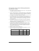
Chapter 1. Introduction TSU Option Modules Some of the option modules available for the TSU 120 are: Name Description DSX-1 Short haul T1 interface for operation with a PBX (Terminal Interface). Full Drop and Insert Permits the dropping of data and insertion of new data into the same DS0 time slot. Includes a long haul DS1 interface. Can be used as a second DS1 interface to provide up to 3 MB aggregate throughput. Nx56/64 Serial Interface Provides a V.
Chapter 1. Introduction Option Module Architecture The TSU 120 features a unique architecture that allows you to add one option module and plug-on board to accommodate another application. See Figure 1-1. DSX-1 Module TSU 120 A 1 TD1 RD1 TD2 RD2 TDN RDN ALM /TST 7 TSU 120e B 2 D 4 C 3 E 5 NEXT SHIFT F 6 PREV 0 OCU-DP Module Plug on V.35 V.35 Module Plug on OCU DP ADD 8 DELET E 9 QUICK # D&I Module DUAL Voice Plug on Dual Voice Figure 1-1.
Installation Chapter 2 UNPACK, INSPECT, POWER UP Receipt Inspection Carefully inspect the TSU 120 for any shipping damages. If you suspect damage, file a claim immediately with the carrier and then contact ADTRAN Customer Service (see inside the last page of this manual). If possible, keep the original shipping container for use in shipping the TSU 120 back for repair or for verification of damage during shipment.
Chapter 2. Installation Power Connection Each TSU 120 is equipped with a captive eight-foot power cord, terminated by a three-prong plug which connects to a grounded power receptacle. Power to the TSU 120 must be from a grounded 90-120 VAC, 50/ 60 Hz source. GROUNDING INSTRUCTIONS Grounding instruction information from the Underwriters' Laboratory UL 1950 3rd Edition, is provided in this section.
Chapter 2. Installation mentary equipment grounding conductor shall be in compliance with the rules for terminating bonding jumpers at Part K or Article 250 of the National Electrical Code, ANSI/NFPA 70. Termination of the supplementary equipment grounding conductor is permitted to be made to building steel, to a metal electrical raceway system, or to any grounded item that is permanently and reliably connected to the electrical service equipment ground.
Chapter 2. Installation Identification of Rear Panel Layout The configuration of the rear panel of the TSU 120e is shown in Figure 2-1. The TSU 120 rear panel is shown in Figure 2-2. Monitor/Test Jacks for DSX-1 DSX-1 Connection 10 Base T Connection for LAN OPTION SLOT 1 Power Switch CAUTION-RISK OF ELECTRIC SHOCK 10 BASE T PORT 0.2 P O W E R SUPPLEMENTAL EARTH GROUND MUST BE CONNECTED PRIOR TO CONNECTION OF TELECOMMUNICATIONS WIRING PORT 0.
Chapter 2. Installation TSU 120 Interfaces The TSU 120 is equipped with a Nx56/64 data port, a DSX-1 interface, an option slot, management interfaces, and a T1 interface, in the rear panel. See Figure 2-3. 10BaseT LAN (TSU 120e only) PC or Modem Control Input Chain Output Chain Input NI TSU 120e Network DSX-1 Nx56/64 PBX V.35 Chain Output NI TSU 120e DSX-1 Nx56/64 Option DSX-1 Option V.35 Figure 2-3.
Chapter 2. Installation DSX-1 (PBX) Interface The DSX-1 Interface provides a short haul T1 for a PBX or other equipment. This port complies with ANSI T1.102. DSX-1 Test Interface The IN and OUT test jacks for the DSX-1 interface provide intrusive test capabilities for the T1 connecting the TSU 120 to the PBX or other customer premise equipment. By connecting to these jacks with test equipment, the DSX-1 connection will be broken, and the test equipment will be terminating the DSX-1 connection from the PBX.
Chapter 2. Installation Power Up Testing When shipped from the factory, the TSU 120 is set to factory default conditions. At the first application of power, the unit automatically executes a memory self-test. A full self-test can be run from the front panel. A passcode and Unit ID may be set using the UTIL MENU. Self-Test Upon a power-up, the LCD displays MEMORY TEST NOW TESTING and the Test LEDs are illuminated.
Chapter 2. Installation Set Chain Port Input The TSU 120 can be configured from the chain port input when T-WATCH Pro, SNMP, or the terminal interface are being used. In this case, the chain port baud rate must also be selected. Chain-In (PC) The unit can be controlled from an external PC connected directly or via modem to the chain-in port.
Chapter 2. Installation At this point, the Unit Initialization procedure is concluded. If the unit is to be configured remotely, there are no additional items necessary to complete prior to executing remote configuration. The Passcode, the Unit ID, and the Control Port settings are stored in a nonvolatile memory. This ensures they are operable for subsequent power-up sequences.
Chapter 2.
Operation Chapter 3 FRONT PANEL The TSU 120 front panel monitors operation and controls the configuration of the unit. The TSU 120 front panel is shown on page 3-3. Figure 3-1 describes each part of the front panel. Table 3-1. Front Panel Descriptions Name 61202129L1-1 Description LCD Window Displays menu items and messages in two lines by 16 characters and alarm and status information. Enter Selects active menu items. To select a menu item, press the number of the item.
Chapter 3. Operation Table 3-1. Front Panel Descriptions Name Description Numeric Keypad The numeric keypad contains the numbers 0 through 9 which are used to activate menu items and enter information (such as the IP address). Shift (entering special function keys) Enter special function keys by pressing and holding Shift before pressing the key representing the desired character. To activate a special function key rather than a number, press and hold Shift; then the button.
Chapter 3. Operation . No Description Action/Status 1 LCD Window Displays menu items and messages in 2 lines by 16 characters 2 Up and Down Arrows Scroll through and activate the submenu items available in the current menu.
Chapter 3. Operation DSU/DSX Status The DSU/DSX status LEDs display the operational condition of the Nx56/64 and DSX-1 parts included in the TSU 120. It also reflects the status of the DBU in the TSU 120e. OK (GREEN) Indicates the operation is in the normal mode and no errors have been detected. TEST (YELLOW) Indicates that one of the interfaces is operating in a test mode. This includes a self-test or a test loopback.
Chapter 3. Operation A LARM (RED) Indicates an alarm condition has been detected. When the alarm condition is no longer valid, the OK LED activates (turns on). To view an alarm condition, select the active alarm menu item or select Alarm by pressing Shift 8. If the alarm conditions have been corrected, the alarm which caused the activation of the Alarm LED can be viewed under the Unit History menu.
Chapter 3. Operation Select and Activate a Menu Item To choose menu items, place the cursor on the desired menu item by pressing the number corresponding to the menu item or highlighting the menu item with the up and down arrow. Activate the ALARM LIST option from the STATUS MENU by using the following steps. Step Action 1 Activate the STATUS MENU using the arrow keys or by pressing 1. The cursor will flash on the number next to the activated selection. 2 Press Enter.
Chapter 3. Operation Set the Data Field You can edit data fields preceded by a colon (:). Step Action 1 Position the cursor on the submenu item number, and press Enter. The cursor moves to the data field, (to the right of the submenu item name). 2 Using the Arrow Keys, scroll to scan the available value settings. The value settings display one at a time in the data field position. 3 When the desired value is displayed in the data field position, press Enter to set that value.
Chapter 3. Operation The equal symbol after LBO in the second line indicates the information that follows is displayed data and cannot be edited. Exit Any Menu Field Operation Or Display Press Cancel as many times as needed to return to the desired menu level or press Shift+0 (Home) to return to the main menu. Data Port Identification When configuring the unit, menu selections will include options from data port submenus.
Chapter 3. Operation Front Panel Menu Structure The TSU 120 uses a multilevel menu structure containing both menu items and data fields. All menu operations and data display in the LCD window. The opening menu is the access point to all other operations. Each Main menu item has several functions and submenus to identify and access specific parameters.
Chapter 3. Operation Alternate Methods of Control T-WATCH Pro (ADTRAN PC Program) T-WATCH Pro is the ADTRAN PC control program. It provides complete control over the configuration of the TSU 120 using a graphical interface. The T-WATCH Pro program displays the same status and performance data as the front panel LCD. This data is displayed in the form of tables and graphs.
Chapter 3. Operation T-WATCH Pro/EIA-232 Connection To set up the TSU 120e to work with T-WATCH Pro over a direct EIA-232 connection, follow these steps: Step Action 1 Set the Unit ID and set a passcode using the front panel. See Unit ID on page page 6-4 and Set a Passcode on page 6-4 for details. 2 Set the control port rate to the same setting as the PC Com port. 3 Connect the PC Com port to the chain-in port on the TSU 120 using the DB25 adapter and modular cable provided.
Chapter 3. Operation To use SNMP via SLIP port, follow these steps: Step Action 1 Set CONTROL PORT to SLIP. 2 Set the IP ADDRESS. The DEFAULT GATEWAY, and SUBNET MASK are not used in SLIP. 3 The appropriate MIB browser must be loaded into the Network Management Station (available on the ADTRAN webpage at http://www.adtran.com). 4 The MIB browser issues SNMP gets/sets to the TSU 120e. Terminal Mode The TSU 120 provides the front panel menus to a VT 100-type terminal.
Status Menu Chapter 4 The Status menu branch provides the ability to view the status of the TSU 120 operation. See Figure 4-1. %AS %EF 1) NI PERF RPTS ES SES 2) NI ERRORS UAS 1)STATUS 3) ACTIVE ALARMS (ALARM LIST) END OF LIST 4 )VIEW HISTORY (HISTORY LIST) END OF HISTORY 1) DTE DATA/CLOCK 5) PORT STATUS 0.1 Nx56/64 2) DTE STATUS 3) PORT RATE 4) DBU DATA/CNTR (TSU 120e) 5) DBU CONTRL (TSU 120e) 6) DBU STATUS (TSU 120e) 6) REMOTE PORT 0.
Chapter 4. Status Menu Network Performance Reports (NI PERF RPTS) The Network Interface Performance Reports display the user copy of the performance data. The TSU 120 maintains this performance data on the network in compliance with ANSI T1.403 and AT&T document TR54016. The data displayed is data accumulated over the last 15 minutes and over the last 24 hours.
Chapter 4. Status Menu Since only the user ’s copy of performance data is cleared by the TSU 120, the data displayed here might be different from the data sent to the network as PRM data. Network Interface Errors (NI ERRORS) The NI ERRORS submenu displays the types of errors the Network Interface (NI) detects. A blinking CSU error LED indicates that network errors are detected. The asterisk (*) above an item indicates the type of errors detected.
Chapter 4. Status Menu Alarm Source Alarm Message Figure 4-3. Display of Alarm Message View History This menu item both displays and clears the accumulated status changes of the unit. View History displays a history of the first 20 status changes in the unit, including the date, time, and type of change. The unit also records for viewing, the date and time an alarm became active and inactive, as well as the date and time of test activation and deactivation.
Chapter 4. Status Menu 0.1 Nx56/64 Menu Items DTE Data/Clock An asterisk (*) indicates an active status of the following lines.
Chapter 4. Status Menu DBU Contrl (TSU 120e only) Request to send to DCE RTS CTS Clear to send from the DCE DTR Data terminal ready to the DCE DSR Data set ready from the DCE DBU Status (TSU 120e only) DBU SECS Total seconds in current DBU session IN DBU YES/NO indication of active DBU status 0.2 DSX-1 Menu Items DSX-1 Errors An asterisk displays under the CRC if there are CRC CRC errors in extended superframe format (ESF) mode.
Chapter 4. Status Menu Remote Port Remote Port displays the status of activity on the control-in remote port. This is useful for troubleshooting communication sessions, and for verifying cabling. RX Characters received at remote port ID Unit ID received at remote port CRC Correct CRC received PC Correct passcode received TX Characters transmitted from the remote port Clear Port Alarm (Clear Port Alm) Clears the Link Failed alarms on option modules that have been removed from the TSU 120 chassis.
Chapter 4.
Chapter 5 Configuration Menu The CONFIGURATION MENU sets the TSU 120 operational configuration, including all network interface parameters, the allocation of the DS0s, and the port parameters. See Complete Configuration Menu on page 5-2. Menu flow is normally depicted from left to right. Arrows on the lower right of the screen indicate the direction of scrolling to view additional menu items. At every level of the menu, pressing Cancel returns the system to the previous menu level.
Chapter 5.
Chapter 5. Configuration Menu NETWORK (NI) This menu item accesses the configuration of parameters associated with the network interface in the base unit. There are nine submenu items that include setting the format, the line build out (LBO), and the timing mode. Submenu items do not include setting the parameters which may be necessary for a secondary interface (DSX-1 Passthru, etc.). Network (NI) Menu Items The menu items are: Menu Item FORMAT Description Sets the frame format for the NI.
Chapter 5. Configuration Menu Menu Item SET LBO Description Selects the line build out for the network interface. In AUTO MODE, the TSU 120 sets the LBO based on the strength of the receive signal and displays the selected value. Choices: 0.0 dB, 7.5 dB, 15 dB, 22 dB, Auto. In order to activate the -36 dB receiver sensitivity, the LBO should be set to AUTO. This feature is useful in a point-to-point application where no network elements are involved.
Chapter 5. Configuration Menu TSU 120 Clock Sources The TSU 120 is operable from various clock sources permitting it to perform properly in many different applications. Set the network interface clocking options with the clocking options set by the Network (NI) Configuration menu options.
Chapter 5. Configuration Menu Network Timed The network is the source of timing. The received data clocking is looped back to the network where it is used to determine the transmission timing. This option is also referred to as loop timed as the transmission clock is derived from the received clock. See Figure 5-2. . Figure 5-2.
Chapter 5. Configuration Menu Base DSX-1 Timing The PBX is the source of timing. The TSU 120 uses the clock derived by the Base DSX-1 interface for transmission timing. See Figure 5-3. OSC T1 XMIT (DS1) T1 Receive Network Interface (OPTION) Nx56/64 DSX-1 DTE CLOCK DTE PBX Figure 5-3.
Chapter 5. Configuration Menu DTE Timing The DTE is the source of timing. The TSU 120 uses the incoming DTE clock to determine the transmission timing. This is typically used in applications where it is necessary to have the DTE as the primary clock source, (such as limited distance line drivers). See Figure 5-4. OSC T1 XMIT (DS1) T1 Receive Network Interface (O P T IO N ) Nx56/64 DSX-1 DTE CLOCK DTE PBX Figure 5-4.
Chapter 5. Configuration Menu Internal Timing The TSU 120 is the source of timing. The TSU 120 is configured to use its own internal oscillator as the source of timing. Applications include private line driver circuits where one end is set to network and the other to internal. See Figure 5-5. OSC T1 XMIT (DS1) T1 Receive Network Interface ( OP TION ) Nx56/64 DSX-1 DTE CLOCK DTE PBX Figure 5-5.
Chapter 5. Configuration Menu Secondary Timing The secondary interface is the source of timing. The TSU 120 uses the clock derived by the secondary interface for transmission timing and the receive signal timing. See Figure 5-6. Either a DSX-1 Option Module or a Drop and Insert Option Module must be installed in the TSU 120 for this mode to function. OSC T1 XMIT (DS1) T1 Receive Secondary Interface (SI) Network Interface (NI) (IO PB) ( OPT IO N ) PBX Nx56/64 DSX DTE CLOCK DTE PBX Figure 5-6.
Chapter 5. Configuration Menu Normal (CSU) Timing In the Normal (CSU) Timing mode, the Receive Clock is derived from the Network Interface while the Transmit Clock is derived from the PBX or other alternative timing source, connected to the Secondary Interface (e.g., Drop and Insert or DSX-1). See Figure 5-7. This timing option is the same as that typically used for CSUs. This is the preferred mode for use with a PBX application. Secondary Interface (SI) Network Interface (NI) (OPTION) Figure 5-7.
Chapter 5. Configuration Menu Unit Menu The Unit menu changes the baud rate of the chain in port and the setup of the dial out port. The menu items are: Menu Item Description Sets the baud rate for communication with the PC or modem. CTL PORT RATE Choices: 1200, 2400, 9600, 19200, and 38400 kbps Enables or disables the transmission of trap messages.
Chapter 5. Configuration Menu Menu Item IP ADDRESS Description This is the IP address that uniquely identifies the TSU 120 on a TCP/IP network. This address is composed of four decimal numbers, each in the range of 0 to 255, separated by periods. This value is used for either the 10BaseT Ethernet or SLIP interface, depending on the IP interface setting (10BaseT is only available in the TSU 120e). SUBNET MASK This defines which part of a destination IP address is the Network number.
Chapter 5. Configuration Menu Map Exchange (Map Xchng) The MAP EXCHANGE menu enables and sets the automatic time of day map switch. The unit provides selection of the hour, minute, and seconds for the map switching to take place. The menu items are: Menu Item Description OFF Indicates the map in use does not change (disabled). AUTO Indicates that the map in use will change at a user-selected time of day (enabled). 1. Scroll to select AUTO to enable or OFF to disable the Automatic Map Change feature.
Chapter 5. Configuration Menu DS0 Map A and DS0 Map B The DS0 maps designate which DS0s are assigned to which port. See Figure 5-8. There are three maps, DS0 MAP A, DS0 MAP B, and the TEMPORARY (TEMP) MAP. TEMP MAP A MAP B Figure 5-8. DS0 Map Designations Map A and Map B are the current maps the TSU 120 uses. The Temp map generates a map before putting it into use. You can copy Map A to Map B by copying the Map A into the TEMP map. Then apply (write) the TEMP map into Map B.
Chapter 5. Configuration Menu Menu Item Description REVIEW TEMP This menu item is operated the same for the Temp Map as is 3)REVIEW MAP A or MAP B. EDIT TEMP The map in the Temp file can be edited to whatever configuration is desired. If Map A had been copied into the Temp file, then after editing, the Temp file could be applied to MAP A or MAP B. The menu operation is identical to 2) CREATE TEMP with the exception that the existing port selections display.
Chapter 5. Configuration Menu With the cursor on CREATE TEMP, press Enter. The unit displays the selection screen with the cursor positioned on the first selection DS0 number. See Figure 5-9. Select DS0 Number Select Port Figure 5-9. Create Temp Selection Screen 1. Use either the Arrow Keys or Numbers to enter the DS0 number (do not mix the use of the keys). 2. Press Enter to complete the selection and move the cursor to Port, the next field. 3.
Chapter 5. Configuration Menu Port Configuration (Port Config) Port Configuration selects and configures the parameters associated with any data port in the unit. For example, parameters for the DSX-1 (PBX) interface are set through this menu. The items that can be set depend on which option module is installed. The list of option ports will vary with the configuration.
Chapter 5. Configuration Menu Menu Item DATA Description Used to control the inverting of the DTE data. This inversion can be useful when operating with an HDLC protocol. Often used as a means to ensure 1s density. Choices: Normal, Invert If Invert is selected, zero (0) inhibit should also be selected to prevent an open DTE input from placing zeros on the network. CTS Used to control characteristics of CTS. Choices: Normal*, Force On *See Table 5-1 on page 5-20. DCD Data Carrier Detect.
Chapter 5. Configuration Menu Menu Item INBAND MODE Description The Nx56/64 port is capable of providing an inband communications channel (for TWatch and SNMP) between units. This is accomplished by using 8 kbps of the first DS0 assigned to that particular Nx56/64 port. If in 56 K mode, no data bandwidth will be used. Inband must also be enabled at the destination port.
Chapter 5. Configuration Menu DBU Configuration Menu Items (TSU 120e only) Menu Items BACKUP MODE Description In a backup condition, both ends of the circuit must detect backup conditions before backup is activated. One DBU is set to ORIGINATE and the other to ANSWER. Upon a network failure, only the Originate DBU initiates backup by dialing the Answer end. Once called, the Answer DBU goes into backup mode only if a backup condition is detected. This is ideal for controlling where calls originate.
Chapter 5. Configuration Menu Menu Items Description RESTORE DELAY Selects the time that elapses between the network going out of alarm or data and the backup call being taken down. If NEVER is selected, the user must deactivate the backup mode. Choices: 1 sec, 3 sec, 10 sec, 30 sec, 1 min, 5 min, 10 min, never RETRY DELAY Selects the time between redialing the external DCE after failed dial attempts.
Chapter 5. Configuration Menu Menu Items ENABLE HR Description The hour backup will be enabled. Enter from the numeric keyboard. Choices: 0-23 DISABLE HR The hour that the backup will be disabled. Enter from the numeric keyboard. Choices: 0-23 For these items to function properly, verify that the time and date in the TSU are set correctly. See Chapter 6, Utility Menu, Time/Date section.
Chapter 5. Configuration Menu Menu Items LINE LENGTH (FT) Description LINE LENGTH provides selection of the proper output level for the base DSX-1 based on the length of the interface cable. Choices: 1-133 ft, 133-266 ft, 266-399 ft, 399-533 ft, 533-655 ft, -7dB IN-BAND LOOPBACK (INBAND LPBACK) IN-BAND LOOPBACK sets the base DSX-1 to accept or reject in-band loopup or loopdown codes (per ANSI T1.403 specification) which may be sent to the card over the DSX-1 interface. This loopback is a line loopback.
Utility Menu Chapter 6 The UTILITY MENU tree displays and sets system parameters (see Figure 6-1 on page 6-2). This includes: • setting the time and date, • resetting all parameters to factory values, or • re-initiating the unit. This menu also displays the unit software revision and the Unit ID setting. Menu flow is normally depicted from left to right. Arrows on the lower right of the screen indicate the scrolling direction to view additional menu items.
Chapter 6. Utility Menu TIME: HH:MM:SS 1) TIME/DATE DATE: MM/DD/YY (Returns all configurations 2) FACT RESTORE to factory settings) 3) SET PASSCODE NEW PASSCODE 3) UTIL VERIFY PASSCODE 4) UNIT ID 5) SOFTWARE REV (Displays Current Software Revision 6) PORT UTILITY 0.1 Nx56/64 0.2 DSX-1 7) ENET ADDRESS (OPTION PORTS) 8) SERIAL NUMBER 9) CMD MODE Figure 6-1.
Chapter 6. Utility Menu Time/Date This menu option displays or edits the current time and date. The TSU 120 maintains the time and date during power-off conditions. If you want to... Do this...
Chapter 6. Utility Menu Pressing any key after entering a passcode causes the unit to return to the previous active menu. In this case it returns to 2)CONFIG, 2)UNIT, 1)CTL PORT RATE, to permit changing the data rate. Change/Set a Passcode The passcode can be changed or set at any time or eliminated altogether through the Utility Menu item 3)SET PASSCODE. This procedure requires the current passcode (if one is established) for operation. The passcode can only be entered by using numbers.
Chapter 6. Utility Menu If an out-of-range number is entered, the unit assumes the upper limit number of 999. Set the Unit Identification In the UNIT ID MENU (item 4) under the UTIL MENU, enter any value between 2 and 999. The number 1 is reserved for the PC. Press Enter to record the Unit ID number and to establish its availability for operation by remote control. The unit proceeds to the SET C ONTROL PORT prompt. No Unit ID Desired Press Enter at the UNIT ID PROMPT without entering any numbers.
Chapter 6.
Test Menu Chapter 7 The TEST MENU initiates different types of unit tests and displays test results in the LCD window. The TEST MENU contains four items (see Figure 7-1 on page 7-2). Executing tests will disrupt some of the normal operation. See individual menu items concerning tests before executing. Menu flow is normally depicted from left to right. Arrows on the lower right of the screen indicate the scrolling direction to view additional menu items.
Chapter 7. Test Menu LINE ON 1) LOCAL LOOPBCK PAYLOAD ON NO LOOPBACK 1) NETWORK TESTS ATT INBAND LLB ANSI FDL LLB 2) REMOTE LOOPBK ANSI FDL PLB FT1 LPBK NO LOOPBACK ALL ZEROS 5) TEST 3) TEST PATTERN QRSS ALL DS0S QRSS TST DS0S ALL ONES NONE 4) PATTERN RESULT (Displays results) 2) RUN SELFTEST (Displays results) 1) DTE LOOPBACK 3) PORT TEST Nx56/64 ( 0.
Chapter 7. Test Menu Network Tests Network tests control the activation of loopbacks and the initiation of data test patterns. Network tests are run on the Network Interface (NI). You can select three different test configurations to determine the type of loopback and the pattern to run. Test results display in the LCD window. Executing NETWORK TESTS will disrupt normal data flow unless only TST DS0S are selected for testing.
Chapter 7. Test Menu TSU 120 NI CSU Secondary Interface DS1 Payload Loopback Line Loopback Figure 7-2. Network Loopback Tests LOCAL LOOPBCK There are three available choices for setting the local loopback: LINE ON Activates the line loopback PAYLOAD ON Activates the payload loopback NO LOOPBACK Deactivates the loopback Using the arrow keys, select a setting and record it by pressing Enter.
Chapter 7. Test Menu FT1 LPBK Initiates the transmission of a FT1 loopback using the inband code described in T1.403. NO LOOPBACK Deactivates the loopback Remote Loopback can only be used with Fractional T1 if the ANSI FT1 LLB is selected. After a Remote Loopback option is selected, the TSU 120 verifies that the far end is actually in a loopback by checking for the receipt of a code looped back from the far end.
Chapter 7. Test Menu QRSS ALL DS0 S Generates a QRSS test pattern and inserts the pattern into all DS0s QRSS TST DS 0S Inserts a QRSS pattern in those DS0s mapped as TST in the currently active map (A or B) NONE Terminates pattern generation QRSS always runs at 64K/DS0. Example 1. Select QRSS ALL DS0S by using the Arrow Keys. 2. Press Enter to record the selection. The TSU 120 starts to generate a QRSS test pattern and inserts the pattern into all DS0s. 3. To end the test, select NONE.
Chapter 7. Test Menu Press Shift+9 to clear results. The results are accumulated until the test pattern is set to NONE or CLEARED. Using TST DS0s for testing can be very useful, particularly in Fractional T1 applications. You can run an end-to-end test on the Fractional DS0s by: 1. Setting for Map B the TST in the same DS0 as used by Map A to receive data from an Nx/DBU port, and 2. Looping the far end using a V.54 loopback code on the Nx/ DBU port (DBU is TSU 120e only).
Chapter 7. Test Menu The self-test consists of the following tests: BOARD LEVEL TESTS Each of the TSU 120 boards contain an on-board processor which executes a series of tests checking the circuitry on the board.
Chapter 7. Test Menu Port Test Menu Items for 0.1 Nx56/64 0.1 Nx56/64 is the base Nx interface. It offers the following test functions: DTE LOOPBK This initiates a loopback. The following options are available: PRT/LCL The Nx port activates both a Local loopback (back toward the DTE) and a Port loopback when either is invoked. REMOTE The remote loopback causes a V.54 code to be sent to the far end. The Nx at the far end activates a PORT/LCL loopback upon detection of the V.54 code.
Chapter 7. Test Menu DBU Loopback (TSU 120e only) Initiates a loopback from the DBU towards the ON external DCE OFF Terminates the loopback test DBU Test (TSU 120e only) This selection is used to force a backup to occur even if a backup condition does not exist. Test Name What it does... TEST OFF Turns off DBU tests FORCED BACKUP Forces a backup regardless of time-of-day lockouts or network conditions INTERFACE TEST Causes the external DCE to dial its stored number.
Telnet/Terminal Menus Chapter 8 MAIN MENU The TELNET/TERMINAL MAIN MENU is the first menu displayed after the TELNET/Terminal session is established. See Figure 8-1. The default TELNET/Terminal password is ADTRAN. Only one TELNET/Terminal session may be active at a time. ADTRAN - TSU 120 Password: XXXXXXXX Main Menu 1) 2) 3) 4) 5) 6) 7) 8) Status Config Util Test Remote Menu Access Management Config Flash Download Quit Session Figure 8-1.
Chapter 8. Telnet/Terminal Menus Status, Config, Util, and Test Menu Options These menu items can access the same modified menus that you can access through the front panel.
Chapter 8. Telnet/Terminal Menus You can use the ARROW KEYS or Number Keys to move the cursor from one selection to another. Use the Enter Key to perform the action displayed in the LCD to the right of the cursor. Map Configuration Map configuration consists of the following steps: Step 1 Action Initialize the Temp Map to one of three configurations: • Current Map A • Current Map B • All Idles This step is optional. 2 Edit the Temp Map so that it reflects the desired map configuration.
Chapter 8. Telnet/Terminal Menus Editing the Temp Map To edit the Temp Map, follow these steps. Step Action 1 To make additional changes to the Temp Map, use Selection 7 to enter the Temp Map edit mode. Explanation: Upon entering this mode, the cursor location moves to DS0 number one in the DS0 field of the Temp Map. The cursor may be moved from one DS0 to another using the Arrow Keys until it is located at the DS0 number whose assigned port needs to be changed.
Chapter 8. Telnet/Terminal Menus Remote Menu Access This displays TELNET menus for a remote device (may be another TSU/TDU or any other ADTRAN product that supports TELNET via its EIA-232 chain port). After selecting this option, the user may: 1. Choose to connect to a device entered in the Unit Access Table or 2. Enter a Unit ID for a unit not listed in the Unit Access Table. CTRL + X terminates the session and returns to the TSU 120 Main menu.
Chapter 8. Telnet/Terminal Menus _____________________________Unit Access ____________________________ Unit ID Passcode Type Polled 20 DEFAULT Standard No 3 0033 Standard Yes 6 0095 TSU Stand Alone No 8 0022 Standard Yes PollStatus UP UP 1) Add New Unit 2) Modify Unit 3) Delete Unit 4) Default Unit Passcode 0022 5) OK Figure 8-3. Unit Access Table Add New Unit This adds a new device to the unit access table.
Chapter 8. Telnet/Terminal Menus Modify Unit Allows UNIT ID, PASSCODE, DEVICE TYPE, and POLLED FLAG to be changed for an existing entry in the table. Delete Unit Deletes an entry in the table. Default Unit Passcode Sets the default passcode for all devices in the table that have passcodes set to DEFAULT, or for any unit not listed in the table. OK Returns to the Configure Agent menu. SNMP Read Community • SNMP Read Community Name defaults to public.
Chapter 8. Telnet/Terminal Menus To access other units external to the TSU 120 (proxied units) using an SNMP MIB browser, append a period and the Unit ID of the external device to the read only and read/write community name used in the MIB Browser; for example, public.4. See Appendix A, Understanding SNMP for more information. SNMP Trap Community This community name is used for all SNMP traps forwarded by the TSU 120.
Chapter 8. Telnet/Terminal Menus System Location A text string describing the physical location of an SNMP managed node (for example, SECOND FLOOR PBX ROOM). Auth. Fail Traps Sent (DISABLED, ENABLED: defaults to DISABLED) When enabled, the TSU 120 issues an SNMP trap when any SNMP request is received with an invalid community name. Can be used for security purposes. Poll Link Status Traps Sent (DISABLED, ENABLED, defaults to DISABLED).
Chapter 8. Telnet/Terminal Menus Flash Download The TSU 120 uses flash memory that allows software updates via the EIA-232 port. This menu selection allows you to manually perform a flash download using XMODEM. T-FLASH is also available to automate this process. Quit Session Terminates the TELNET/Terminal session.
Appendix A Understanding SNMP ABOUT SNMP As local area network (LAN) environments became standardized over the past ten years, multi-vendor equipment grew with competition. It became necessary to manage the various vendor equipment from a single control console. Thus, the SNMP emerged as the standard for managing commercial TCP/IP networks.
Appendix A. Understanding SNMP MIB This is an index to the organized data within a network device. It defines the operating parameters that can be controlled or monitored. When requesting the network manager to retrieve or modify a particular piece of information about a network device, the network manager transmits the request to that network device. The agent in that device interprets the incoming request, performs the requested task, and sends its response to the network manager.
Appendix A. Understanding SNMP Trap This is an unsolicited message issued by a network device to report an operational anomaly or an alarm condition to the network manager. These messages are typically encased within informational packets and transported over the LAN or WAN (wide area network). TSU 120 SNMP Access By default, SNMP MIB Browser access to the TSU 120 IP address with the configured community names, accesses the host. The TSU 120 can also act as an SNMP proxy agent for external units.
Appendix A. Understanding SNMP SNMP Trap Configuration Traps received by the TSU 120 from external units and the host unit are converted into SNMP traps and forwarded to the configured NMS. The source of the trap is uniquely identified at the NMS by a combination of the IP address of the TSU 120, and the Unit ID of the sending device. The Unit ID is present in the trap packet appended to the end of the trap community packet name, for example public.4.
Appendix A. Understanding SNMP SNMP MIB BROWSER CONFIGURATION The following steps, shown in Table A-1 are required to configure Network Manager MIB variable access through the TSU 120: Table A-1. How to Configure Network Manager MIB Step Action 1 Load the desired product MIBs on the network management station. If, for example, the administrator is managing TSU 120 and ISU 512 devices, load TSU 120.MIB, ISU512.MIB, and RFC1406.MIB.
Appendix A. Understanding SNMP SNMP MIB Files Supported by the TSU 120 Standard MIBs MIB-II (RFC-1213) DS1 T1/E1 MIB (RFC-1406) Ethernet MIB (RFC-1643) (TSU 120e) ADTRAN Enterprise-specific MIBs ADTRAN Product MIB (ADTRAN.MIB) ADTRAN DS1 extensions MIB (ADS1.MIB) TSU/TDU Enterprise MIBs (TSU 120e.MIB) The standard MIB files are The latest version of the ADTRAN enterusually included with most prise specific MIBs are available from the SNMP network management following sources: software.
Appendix B Understanding TR-08 The TSU 120 chassis functions as a Remote Terminal in Digital Loop Carrier and as Integrated Digital Loop Carrier Systems as described in TR-TSY 000008. The TSU 120 supports SLC96 framing, Mode I operation, ORB-13 and ORB-16 alarm formats, alarm reporting, and user-definable BPV threshold detection rate.
Appendix B. Understanding TR-08 Table B-1 explains what conditions trigger alarms and how alarms are processed when received by the TSU 120. Table B-1. Alarm Conditions Name Explanation FELP When the TSU 120 receives a FELP alarm, it will loop the incoming data directly to the outgoing data. LINE ON is placed in history. The alarms and loopback are cleared when FELP is no longer received. Loss of Data The TSU 120 will send MINOR ALARM and the A SHELF ALARM for 2.
Appendix B. Understanding TR-08 TR-08 DS0 Conversion Table Table B-2 contains the mapping conversions needed to map voice ports to the TR-08 network. Table B-2. TR-08 DS0 Conversion Table 612020129L1-1 DS0 TR-08 Channel Number Port 1 1 1.1 3 2 1.2 5 3 1.3 7 4 1.
Appendix B.
Network Pinouts Appendix C WIRING Network Pinouts On the rear panel of the TSU 120 is an eight-position modular jack labeled NETWORK. This connector is used for connecting to the network. See Table C-1 for the pinout for the network connector. Connections The network connections are as follows: Connector type Part number (USOC) RJ-48C AMP# 555164-2 Table C-1.
Appendix C. Network Pinouts Control In/Chain In This is used as an EIA-232 port for connection to a computer or modem (Control In) or to another TSU 120 or TSU 100 (Chain In). See Table C-2 for the pinout for the control/chain-in connector. Connections The chain-in connections are as follows: Connector type Part number RJ-48 AMP# 555164-2 Table C-2.
Appendix C. Network Pinouts Chain Out This is used to connect to another TSU 120 chain-in connector. See Table C-3 for the pinout for the chain-out connector. Connections The chain-out connections are as follows: Connector type Part number RJ-48 AMP# 555164-2 Table C-3. Chain Out Pinout Pin Name 1 GND 2 UNUSED 3 TX DATA 4 UNUSED 5 RX DATA 6,7,8 UNUSED 61202129L1-1 Description Ground - connected to unit chassis. Connected to GND of next unit (pin 10).
Appendix C. Network Pinouts Nx56/64 DTE (V.35) See Table C-4 for the V.35 pinout Nx56/64 DTE pinout. Connections The DTE interface pinout is as follows: Connector type Part number V.35 AMP# 92-4883-3-x Table C-4. V.
Appendix C. Network Pinouts Base DSX-1 (PBX) See Table C-5 for Base DSX-1 pinout connections for either-position Modular Jack Interface. Connections The modular jack interface pinout is as follows: Connector type RJ-48C Table C-5.
Appendix C. Network Pinouts 10BaseT (TSU 120e only) 10BaseT is used to connect the TSU 120 to the local area network. See Table C-6. Connections The required wiring connections are: Connector type (USOC) Part number RJ-45 AMP # 555164-1 Table C-6.
System Messages Appendix D This appendix lists and defines the alarm and status messages that appear on the TSU 120 screen.
Appendix D.
Appendix D. System Messages Nx56/64 Interface The following messages indicate the status of the Nx56/64 card: Loop Up Data is looped at both the network interface and DTE interface of the card Remote Loop Up Sending V.
Appendix D.
Specifications Appendix E ELECTRICAL SPECIFICATIONS T1/FT1 Interface T1 Line Rate 1.544 Mbits/s +/- 75bps Line Code Bipolar,RZ; AMI or B8ZS Framing D4(SF), ESF, or SLC96 FT1 Line Rate DS0 Channelized (multiple of 64 kbps) Transmit Timing Network, DTE, U-BR1TE Secondary NI, Normal (CSU) or Internal Input Signal 0 to -36 dB (DS-1) Line-Build-Out 0, 7.5, 15, 22.
Appendix E. Specifications Nx56/64 (V.35 Interface) DCE Interface CCITT V.35 Synchronous Rates 56kbps - 1.536Mbps in 56k or 64k increments Clock Options Normal/Inverted and internal/external Tests Local Loopback (bilateral)Remote Loopback (V.54) Test Pattern 511 with errored seconds display and error inject capability Data inversion Menu selectable 1s Density Protection Force 1s to network after one second of consecutive zeros from DTE.
Appendix E. Specifications MANAGEMENT INTERFACES Chain In/Out Ports Interface Devices PC Serial Port, Modem or SLIP connection to router Interface Type EIA-232 Data Rates 2400, 1200, 2400, 4800, 9600, 19200, 38400 Data Format EIA-232 N81 Protocols T-WATCH/ADLP, ATEL/ADLP, TCP/ IP/SLIP Connector RJ-45 10BaseT Interface (TSU 120e only) Interface IEEE 802.
Appendix E. Specifications Environmental Specifications Input Power 90-120VAC, 47-63 Hz Fuse 0.6A, 250V Operating Temperature 0 deg C to 45 deg C Max Power 15 Watts Consumption Max Current E-4 0.
Index Numerics 0.1 Nx56/64 Menu Items 4-5 0.1 Nx56/64 Port Configuration (Port Config) Menu Items 5-18 0.2 DSX-1 Menu Items 4-6 10BaseT Interface (TSU 120e) 2-6 10BaseT Interface, management interface E-3 10BaseT, pinouts C-6 A Active Alarms, list of 4-3 ADTRAN PC Management Program 3-10 ADTRAN PC Program, T-WATCH Pro 3-10 ADTRAN shipment, items included in 2-1 ADTRAN Web Site iii ADTRAN Year 2000 (Y2K) Readiness Disclosure iii Affidavit for connection of CPE to 1.
Index default unit passcode, how to set in unit access table 8-7 Delete Unit, how to in unit access table 8-7 Dial backup, option module 1-3 Display Only Data Fields, what they do 3-7 DS0 Map A and DS0 Map B 5-15 DS0 Map Example 5-16 DS0 Temp Map 8-2 DSU DP, option module 1-3 DSU/DSX Status LEDs 3-4 DSX-1 (PBX) Interface 2-6 DSX-1 (PBX) Interface, system messages D-2 DSX-1 Interface E-2 DSX-1 interface status message D-3 DSX-1 Test Interface 2-6 DSX1, option module 1-3 DTE Timed Clock Source 5-8 DTE timing
Index menu tree, status 4-1 menu tree, test menu 7-2 menu tree, utility 6-2 MIB browser configuration, SNMP A-5 MIB, SNMP component A-2 Modify Unit, how to in unit access table 8-7 Module Status LEDS 3-4 N Network (NI), configuration menu 53 Network Interface Errors 4-3 Network Interface Loopbacks, test menu 7-3 Network Interface port 2-5 Network Manager MIB, how to configure A-5 Network Manager, SNMP component A-1 network menu items, configuration menu 5-3 network performance reports 4-2 Network Pinouts C
Index REMOTE LOOPBCK, test menu 7-4 remote menu access, telnet menus 8-5 Remote Port, displaying status on control-in remote port 4-7 repair and return information xiii Router, option module 1-3 Router, PBX, Video Conferencing Applications 1-4 Run Self-test 7-7 Run Self-Test, test menu 7-7 S Safety instructions xii secondary timing, clock source option 5-10 Self-Test, on power-up 2-7 Serial Number, utility menu 6-5 Set Chain Port input 2-8 Set the Data Field, how to 3-7 Set the Unit Identification 6-5 Set
Index Voice Interface, option module 1-3 W Warranty and Customer Service xiii Wiring C-1 61202129L1-1 Y Y2K Compliance iii Y2K Project Line iii Y2K, Faxback Document Line iii TSU 120e User Manual Index-5
Index Index-6 TSU 120e User Manual 61202129L1-1
Product Support Information Presales Inquiries and Applications Support Please contact your local distributor, ADTRAN Applications Engineering, or ADTRAN Sales: Applications Engineering (800) 615-1176 Sales (800) 827-0807 Post-Sale Support Please contact your local distributor first. If your local distributor cannot help, please contact ADTRAN Technical Support and have the unit serial number available.