
Service manual

SERVICE MANUAL
ENGLISH
Adnity
TM
17 ST, 20 ST, 20 D, X 20 D, X 20 C, X 24 D 9096982000(1)2007-02
47
DRIVE SYSTEM
TRACTION ENABLING MICROSWITCH ADJUSTMENT/REPLACEMENT (For Adnity
TM
20 D, X 20
D, X 20 C, X 24 D)
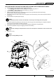
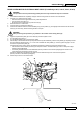
Drive the machine on a level oor.
Turn the ignition key (80) to “0”.
Disconnect the battery connector (12).
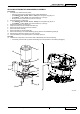
Remove the screws (A) and move the drive paddle cover (B).
Check that the springs (C) operate correctly when releasing the drive paddle (D).
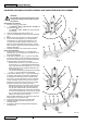
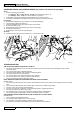
If necessary, replace the microswitch (F) according to the following procedure:
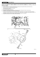
Mark the position of the connectors (I) and disconnect them from the microswitch.
Remove the screws (M).
Remove the microswitch (F).
Install the new microswitch and fasten it with the screws, then connect the connectors (I).
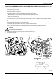
Check that the actuator (E) of the microswitch (F) is in the position (G) of the cam (H) when the drive paddle is released
(D).
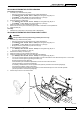
Press the drive paddle (D) and check that the actuator (E), in the position (K) doesn’t activate the microswitch (F). Also
check that the cable contacts (I) are all open (use a tester).
Press the drive paddle (D) and check that the actuator (E), in the position (J) activates the microswitch (F) (a clicking sound
must be heard). Also check that the cable contacts (I) are all closed (use a tester).
If necessary, to reach the above-mentioned condition, loosen the screws (L) and adjusting the position of the cam (H),
and/or by loosening the screws (M) and adjusting the position of the microswitch (F). Retighten the screws.
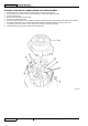
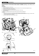
CAUTION!
If the microswitch connections (I) are disconnected, pay attention to reconnect them on the same terminals
and to leave the terminal (N) free.
Assemble the components by performing steps 3 and 4 in the reverse order.
Test the traction operation.
1.
2.
3.
4.
5.
6.
•
•
•
•
7.
8.
9.
10.
11.
B
A
A
D
D
C
C
F
F
P
I
I
I
N
N
H
H
L
L
E
E
M
M
M
G
G
K E J
H G
K E J
O G
O
S301559A