
Service manual

FORM NO. 56043098 - Convertamatic
™
24C, 24D, 26C, 26D, 28C, 28D - 39
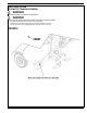
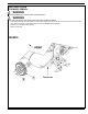
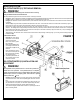
WHEEL DRIVE SYSTEM
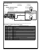
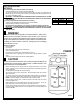
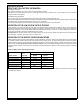
R2 Voltage Values R1 Voltage Values
0V = Minimum Speed 0 – 2.5V Forward
5V = Maximum Speed 2.5V – 5V Reverse
This drawing shows additional controller input circuit detail. The R2 pot is shown at the Max speed setting and the R1 pot in neutral.
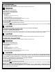
LOW CURRENT A1 SPEED CONTROL PIN KEY DETAIL
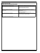
PIN# WIRE COLOR CONTROLLER DESCRIPTION & FUNCTION
1 - Open not used
2 - Open not used
3 Black Throttle Pot R1 pot high input
4 Blue Throttle Pot R1 pot wiper input
5 Brown KSI (key switch input): Battery (+) powers up controller logic circuits.
6 Red/Blk Auxiliary Driver: Battery (-) output to main controller (E1) to turn on (activate) all auto scrub functions.
7 - Open not used
8 - Open not used
9 Orn/Blu Status Fault: Speed controller fault output to main control panel fault indicator light (accessory wand).
10 - Open not used
11 - Open not used
12 - Open not used
13 White Throttle Pot R1 pot low input
14 - Open not used
15 - Open not used
16 Blu/Blk Rev/Alarm Driver output Battery (-) command turns off solution Valve.
17 - Open not used
18 Brown Speed limit pot input connection.
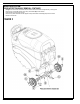
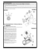
WHEEL DRIVE SYSTEM
A1 Speed Control
Pin Connection
3
5
1
3
18
9
6
1
6
4
POT HIGH
POT
WIPER
POT
LOW
SPEED
LIMIT
KSI
R1 Throttle
5K Ohms
100K Ohms
R2 Speed Limit
WHT
BLU
BRN
BLK
BLK
WHT
POT
REV.
STATUS
BRAKE
BLK
WHT
1
1
2
2
3
3
FIGURE 3