
Service manual

44 - FORM NO. 56043098 - Convertamatic
™
24C, 24D, 26C, 26D, 28C, 28D
WHEEL DRIVE SYSTEM
(5K) POTENTIOMETER (R1) TESTING AND REMOVAL
WARNING!
Disconnect batteries at the battery pack disconnect before servicing.
Testing the 5KDirectional/Throttle Potentiometer R1
Note: The potentiometer (pot) doesn’t have to be removed from its housing mount to test.
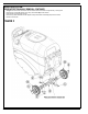
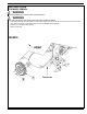
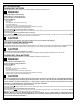
1 See Figure 7. Remove the front Drive Paddle Cover (G) from the Rear Housing (H) held together with (4) (I) Screws. Note the cover will have the speed limiting
Pot (R2) mounted to it, observe the (3) wires and separate them to complete the removal of the cover.
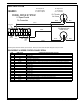
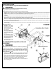
2 See Figure 8. Observe the 3 wires connected to the R1 pot and disconnect. Note the proper wire numbers and/or colors and their terminal connections for
re-assembly.
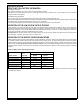
3 Test the Pot (R1) using an ohmmeter, the potentiometer specifi cation is 5K Ohms. Connect the meter leads to each of the outside connections (3 high & 1 low,
shown in Figure 8) on the pot, it should read approximately 5,000 ohms (range 4,500-5,500 ohms).
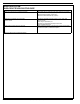
4 Next, take the 3 high pot connection test lead and connect to the middle connection (2 wiper), then push and pull the rear cover to turn the shaft in both
directions. The readings should be approximately half the total resistance (2,500 ohms) towards 5,000 ohms and 2,500 ohms towards 0 ohms. Example “A”:
total resistance of pot 4,840 ohms (3 high/1 low) test connections. Example “B”: test middle connection (2 wiper) and outside rear (1 low) Fwd reading 2,420
ohms to 4,700 ohms, Rev 2,420 ohms to 230 ohms.
5 Testing Summary: The above tests are to show the increase and decrease of the pot through its working range. If you do not get similar readings replace the
Potentiometer (R1).
FIGURE 7
R1 Potentiometer Removal
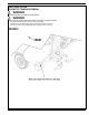
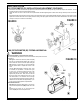
6 See Figure 9. Loosen the pot
shaft anchor nut and unthread
it to the end of the shaft.
7 Back out the Screw (J) from
the pot Fork (K).
8 Maneuver the pot (R1) out from
its mounting bracket hole and
separate the Fork (K) from the
shaft end.
9 Finish unthreading the anchor
nut from the end of the pot and
then remove the pot completely
from the handle mount.
10 To reinstall a potentiometer see
the adjustment section below
in this manual section.
(5K) POTENTIOMETER (R1) INSTALLATION AND
ADJUSTMENT
WARNING!
The adjustment of the potentiometer is to set the drive paddle for a
neutral drive motor operation. If the potentiometer is not adjusted
properly, the machine will not move in either FWD or REV with normal
operator input. Also the Led display panel would indicate a speed
control system fault 03.
1 See Figure 9. Install lock washer (on pot side), pot and anchor nut to the handle
mount bracket as shown. NOTE: Do not completely tighten the anchor nut at this
time.
2 Using an ohmmeter connect leads to the middle terminal (2 wiper) and the (1 low
pot) outside terminal. Then preset, turn the shaft to approximately 2,500 ohms.
3 Install the Fork (K) onto the pot shaft, and then tighten the (J) Screw.
4 Then without turning the pot shaft thread the anchor nut just enough to seat the
pot to its mounting bracket.