User Manual CDE570AM-U02 WiFi Broadband Router 1
Copyright The contents of this publication may not be reproduced in any part or as a whole, stored, transcribed in an information retrieval system, translated into any language, or transmitted in any form or by any means, mechanical, magnetic, electronic, optical, photocopying, manual, or otherwise, without the prior written permission. Trademarks All products, company, brand names are trademarks or registered trademarks of their respective companies. They are used for identification purpose only.
TABLE OF CONTENTS Copyright...................................................................................................... 2 FCC Interference Statement .................................................................... 2 Chapter 1 Introduction .................................................................................... 5 1.1. Package List...................................................................................... 5 1.2. Hardware Installation ......................................
3.4.5.4. SNMP ....................................................................................... 52 3.4.5.5. Routing..................................................................................... 53 3.4.5.6. System Time ........................................................................... 53 3.4.5.7. Scheduling............................................................................... 54 3.4.6. Tool Box.....................................................................................
Chapter 1 Introduction Congratulations on your purchase of this outstanding product: WiFi Broadband Router. This product is specifically designed for those who need to have the file sharing and P2P download services beyond his home and office. It provides a complete solution for Internet surfing and broadband sharing. Instructions for installing and configuring this product can be found in this manual.
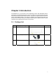
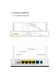
1.2. Hardware Installation 1.2.
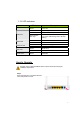
1.2.2 LED indicators LED Status Status LED USB LED WAN LED Ethernet LED WiFi LED Power LED Description Green Power ON Green Green in flash USB storage attached Data access Green in flash then stop Press ‘USB off’ button till LED flashing, then can remove USB storage when LED stop flashing. Green It is connected to local Ethernet.
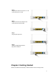
Step 2. Plug the RJ45 cable into LAN port 1~4 and connect with your PC or NB. Step 3. Plug your RJ-45 into the WAN port and connect with your xDSL modem. Step 4. Plug the power jack into it. Step 5. Prepare a USB Storage and then plug into the USB port. Chapter 2 Getting Started Please use windows EZ setup utility or Web UI wizard to enter the setup process.
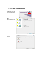
2.1. Easy Setup by Windows Utility Step 1. Install the Easy Setup Utility from the provided CD then follow the steps to configure the device. Step 2. Select Language then click “Next” to continue. Step 3. Then click the “Wizard” to continue.
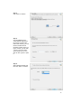
Step 4. Click “Next” to continue. Step 5. One free DDNS account ‘ MAC address.ezguard.net’ for end user to access the NAS router remotely, you can rename an alias name to remember it easily. Once you type in a name, you can click ‘ check’ to see if the name server accept it or not. You also can click ‘Ignore’ to pass it. Step 6. Select Wireless Enable, and then click “Next” to continue.
Step 7. Enter SSID, Channel and Security options, and then click “Next” to continue. Step 8. Select Auto Detect WAN service. Step 9. Save the setting.
Step 10. Congratulations! Setup is completed. Now you have already connected to Internet successfully.
2.2. Easy Setup by Configuring Web UI You can also browse UI of the web to configure the device. Browse to Activate the Setup Wizard Type in the IP Address (http://192.168.123.254) Type the default Username and password ‘admin’ in the System Password and then click ‘login’ button. Select your language. Select “Wizard” for basic settings in simple way. Press “Next” to start the Setup Wizard.
Configure with the Setup Wizard Step 1 You can change the password of administrator here. Step 2 Select Time Zone. Step 3 You can select Auto detecting WAN type or setup WAN type manually.
Step 4 The system will detect the WAN type if you choose to let the system detect automatically. Step 5 Type in Host name and ISP registered MAC address. (if no such information, you can go next) Step 5-1 Wireless setting. Step 5-2 Wireless authentication and encryption.
Step 6 Check the information again. Step 7 System is applying the setting. Step 8 Click finish to complete it.
Chapter 3 Making Configuration Whenever you want to configure your network or this device, you can access the Configuration Menu by opening the web-browser and typing in the IP Address of the device. The default IP Address is: 192.168.123.254. Enter the default username and password “admin” in the System Password and then click ‘login’ button. Afterwards, select ‘Advanced’ indicated in the user interface for further configuring this device.
3.1. Basic Setting 3.1.1. Network Setup There are two ways to configure the network, respectively LAN Setup and Internet setup. 3.1.1.1 LAN type 1. LAN IP Address: The local IP address of this device. The computer on your network must use the LAN IP address of this device as their Default Gateway. You can change it if necessary. 2. Subnet Mask: Input your Subnet mask. (All devices in the network must have the same subnet mask.) The default subnet mask is 255.255.255.0. 3.1.1.1 Internet Setup 1.
Ethernet WAN A. Static IP Address 1. WAN IP Address, Subnet Mask, Gateway, Primary and Secondary DNS: Enter the proper settings provided by your ISP. 2. NAT disable: The device would not send private IP to other LAN PC if you select disable. B. Dynamic IP Address 1. Host Name: Optional, required by some ISPs, for example, @Home. 2. ISP registered MAC Address: Enter MAC address of your ISP. (Optional) 3.
Auto Reconnect (Always-on): The device will link with ISP until the connection is established. Manually: The device will not make the link until someone clicks the connect-button in the Status-page. 4. NAT disable: The device would not send private IP to other LAN PC if you select disable. C. PPP over Ethernet 1. PPPoE Account and Password: The account and password your ISP assigned to you. For security, this field appears blank. If you don't want to change the password, leave it blank. 2.
connect-button in the Status-page. 3. Maximum Idle Time: the amount of time of inactivity before disconnecting your PPPoE session. Set it to zero or enable “Auto-reconnect" to disable this feature. 4. PPPoE Service Name: Optional. Input the service name if your ISP requires it. Otherwise, leave it blank. 5. Assigned IP Address: It is required by some ISPs. (Optional) 6. Maximum Transmission Unit (MTU): Most ISP offers MTU value to users. The default MTU value is 0 (auto). 7.
you. If you don't want to change the password, keep it blank. 5. Connection ID: Optional. Input the connection ID if your ISP requires it. 6. Maximum Idle Time: the time of no activity to disconnect your PPTP session. Set it to zero or enable “Auto-reconnect” to disable this feature. If Auto-reconnect is enabled, this device will connect with ISP automatically after system is restarted or connection is dropped. 7.
and designated Gateway provided by your ISP. 4. L2TP Account and Password: The account and password your ISP assigned to you. If you don't want to change the password, keep it blank. 5. Maximum Idle Time: The time of no activity to disconnect your L2TP session. Set it to zero or enable “Auto-reconnect” to disable this feature. If Auto-reconnect is enabled, this device will connect with ISP automatically, after system is restarted or connection is dropped. 6.
4. Domain Name: Optional, this information will be passed to the clients. Press “More>>” and you can find more settings. 5. Primary DNS/Secondary DNS: Optional. This feature allows you to assign a DNS Servers 6. Primary WINS/Secondary WINS: Optional. This feature allows you to assign a WINS Servers 7. Gateway: Optional. Gateway Address would be the IP address of an alternate Gateway. This function enables you to assign another gateway to your PC, when DHCP server offers an IP to your PC.
3.1.3 Wireless Settings Wireless settings allow you to set the wireless configuration items. 1. Wireless Module: You can enable or disable wireless function. 2. Network ID (SSID): Network ID is used for identifying the Wireless LAN (WLAN). Client stations can roam freely over this device and other Access Points that have the same Network ID. (The factory default setting is “default”) 3.
z Open Open system authentication simply consists of two communications. The first is an authentication request by the client that contains the station ID (typically the MAC address). This is followed by an authentication response from the AP/router containing a success or failure message. An example of when a failure may occur is if the client's MAC address is explicitly excluded in the AP/router configuration.
Another encryption options for WPA-PSK-TKIP and WPA2-PSK-AES, the others are same as the WPA-PSK. z WPA/WPA2 Another encryption options for WPA-TKIP and WPA2-AES, the others are same the WPA. Press “WDS Setting” and It allows PC to get connected to wireless network within the area. 1. Wireless Bridging: You could enable this function by selecting “Enable”. 2. Remote AP MAC 1~Remote AP MAC 2: Enter the wireless MAC into the blank. 3. Encryption type: Select the appropriate category.
1. WPS:.You can enable this function by selecting “Enable”. WPS offers a safe and easy way to allow the wireless clients connected to your wireless network. 2. AP PIN: You can press Generate New Pin to get an AP PIN. 3. Config Mode: Select your config Mode from “Registrar” or “Enrollee”. 4. Config Status: It shows the status of your configuration. 5. Config Method: You can select the Config Method here from “Pin Code” or “Push Button”. 6.
3.1.4 Change Password You can change the System Password here. We strongly recommend you to change the system password for security reason. Click on “Save” to store your settings or click “Undo” to give up the changes.
3.2. NAS Configuration 3.2.1. Disk Utility 1. Format This utility would format the certain partition. Please be noted! This action will clear all your data in this partition. You will not be able to recover it any more. 2. Check This utility could help you check the partition, find the lost files, try to fix some problems. 3.2.2. File Sharing 3.2.2.1. Basic Setting These settings are for Samba Server (Windows Network Neighbors). 1.
3.2.2.2. FTP Service These settings are for FTP service. 1. FTP Port: The default port is 21, but sometimes you might want to hide your FTP service by changing it. We have the ability to receive the request on non-standard FTP port, but please be noted, some NAT router could not support non-standard FTP port, that means some of your clients might have to use passive mode to get file. 2. Client Support UTF8: This option is used when your FTP client could support UTF8.
3.2.3.1. User Configuration In this page, you can manage the user account. Key in the user name and password then press “Add” could let you add a new user. If you want to delete an account, select it and click “Delete” button. 3.2.4. iTunes Server This function could enable the built-in iTunes Server to support iTunes which is a media player released by Apple. 1. Server Name: The name of this server, it will be shown on the iTunes. 2.
3.3.1. FTP If you want to download something from a FTP site regularly but you don’t want to spend time on remembering doing this, this FTP download assistant could help you. 1. Job Name: It’s for you to remember the job easily, and the device would use this name to info you when the job is done. 2. URL: The URL for the file you want to download. You have to use this format: IP/path/file, you don’t have to add protocol part such like “ftp://”. 3.
1. Job Name: It’s for you to remember the job easily, and the device would use this name to info you when the job is done. 2. URL: The URL for the file you want to download. You have to use this format: IP/path/file, you don’t have to add protocol part such like “http://”. 3. Save To: The destination path on USB disk that you want to save files. Default value is /C/Download/HTTP 4. Start Time: Schedule: this device will start FTP download on the time that you specified.
3.3.3. BT (Bit Torrent) 3.3.3.1. Start BT download First, you have to get a seed file, which we called “torrent”. Then click the “Open” link on UI, it would pop up a sub menu to let you upload. Or, if your torrent file could be download from network, you could just enter a URL. 3.3.3.2.
After you upload the torrent, download job would be started immediately. The device could support 3 concurrent download jobs, other jobs would wait in job queue. If one of the three running job is done, the next new job would be started. At this page, you could see the download process and the bandwidth. 3.3.3.3. Stop, Resume and Remove seed Select any job on the list, and click right button of mouse, you could see a menu with several actions you could do.
3.3.4. Download Status At this page, you could check the download jobs of HTTP and FTP. 3.3.5. How to access data on the NAS? 3.3.5.1. Windows User 3.3.5.1.1. By network place Then start your “file manager”, type the IP with “\\” on the beginning, as follow picture shown. Then press enter.
You could find a folder named “Storage”. It is what you are looking for. 3.3.5.1.2. By Web HDD This Web HDD can allow you to enter HDD by web UI, and also can allow you to let ‘guest’ to enter the ‘public’ area only. 3.3.5.2. Unix User We do not provide NFS support, so the only way for UNIX to get files is FTP. Use your FTP client to connect the FTP server.
3.4. Forwarding Rules 3.4.1. Virtual Server This product’s NAT firewall filters out unrecognized packets to protect your Intranet, so all hosts behind this product are invisible to the outside world. If you wish, you can make some of them accessible by enabling the Virtual Server Mapping.
redirected to the computer specified by the Server IP. Virtual Server can work with Scheduling Rules, and give user more flexibility on Access control. For the details, please refer to Scheduling Rule. For example, if you have an FTP server (port 21) at 192.168.123.1, a Web server (port 80) at 192.168.123.2, and a VPN server at 192.168.123.6, then you need to specify the following virtual server mapping table: Service Port Server IP Enable 21 192.168.123.1 V 80 192.168.123.2 V 1723 192.168.123.
the DMZ host instead. This device provides some predefined settings. Select your application and click “Copy to” to add the predefined setting to your list. 1. Trigger: The outbound port number issued by the application. 2. Incoming Ports: When the trigger packet is detected, the inbound packets sent to the specified port numbers are allowed to pass through the firewall. Afterwards, Click on “Save” to store your settings or click “Undo” to give up the changes. 3.4.3.Miscellaneous 1.
this function, and you enabled it, like Windows XP, you can see the following icon when the client computer gets IP from the device. Afterwards, click on “Save” to store your settings or click “Undo” to give up the changes. 3.4.4. Security Setting 3.4.4.1. Packet Filters Packet Filter includes both outbound filter and inbound filter. And they have same way to setting. It enables you to control what packets are allowed to pass the router. Outbound filter applies on all outbound packets.
two filtering policies: 1. Allow all to pass except those match the specified rules. 2. Deny all to pass except those match the specified rules. You can specify 8 rules for each direction: inbound or outbound. For each rule, you can define the following: • Source IP address • Source port • Destination IP address • Destination port • Protocol: TCP or UDP or both. • Use Rule# For source or destination IP address, you can define a single IP address (4.3.2.1) or a range of IP addresses (4.3.2.1-4.3.2.254).
3.4.4.2. Domain Filters Domain Filter prevents users under this device from accessing specific URLs. 1. Domain Filter: Check if you want to enable Domain Filter. 2. Log DNS Query: Check if you want to log the action when someone accesses the specific URLs. 3. Privilege IP Address Range: Setting a group of hosts and privilege these hosts to access network without restriction. 4. Domain Suffix: A suffix of URL can be restricted, for example, ".com", "xxx.com". 5.
1. URL Blocking: Check if you want to enable URL Blocking. 2. URL: If any part of the Website's URL matches the pre-defined word, the connection will be blocked. For example, you can use pre-defined word "sex" to block all websites if their URLs contain pre-defined word "sex". 3. Enable: Check to enable each rule. Afterwards, click on “Save” to store your settings or click “Undo” to give up the changes. 3.4.4.4.
1. MAC Address Control: Check “Enable” to enable the “MAC Address Control”. All of the settings in this page will take effect only when “Enable” is checked. 2. Connection control: Check "Connection control" to enable the controlling of which wired and wireless clients can connect with this device. If a client is denied to connect with this device, it means the client can't access to the Internet either.
1. Administrator Time-out: The time of no activity to logout automatically, you may set it to zero to disable this feature. 2. Remote Administrator Host/Port In general, only Internet user can browse the built-in web pages to perform administration task. This feature enables you to perform administration task from remote host. If this feature is enabled, only the specified IP address can perform remote administration. If the specified IP address is 0.0.0.
3.4.5.1. System Log This page supports two methods to export system logs to specific destination by means of syslog (UDP) and SMTP(TCP). The items you have to setup include: 1. IP Address for Syslog: Host IP of destination where syslog will be sent to. Check Enable to enable this function. 2.
email). 3. SMTP Server: Port: Input the SMTP server IP and port, which are connected with ':'. If you do not specify port number, the default value is 25. For example, "mail.your_url.com" or "192.168.1.100:26". 4. SMTP Username: Enter the Username offered by your ISP. 5. SMTP Password: Enter the User name offered by your ISP. 6. E-mail Addresses: The recipients are the ones who will receive these logs. You can assign more than 1 recipient, using ';' or ',' to separate these email addresses. 7.
select. 5. Password/Key: Input password or key based on the DDNS provider you select. Afterwards, click on “Save” to store your settings or click “Undo” to give up the changes. 3.4.5.3. QoS QoS provide different priority to different users or data flows, or guarantee a certain level of performance. 1. QoS Control: Check Enable to enable this function. 2. Bandwidth of Upstream: Set the limitation of upstream bandwidth. 3. Local IP : Ports: Define the Local IP address and ports of packets. 4.
changes. 3.4.5.4. SNMP In brief, SNMP, the Simple Network Management Protocol, is a protocol designed to give a user the capability to remotely manage a computer network by polling and setting terminal values and monitoring network events. 1. Enable SNMP: You must check “Local”, “Remote” or both to enable SNMP function. If “Local” is checked, this device will respond request from LAN. If “Remote” is checked, this device will respond request from WAN. 2.
3.4.5.5. Routing If you have more than one routers and subnets, you will need to enable routing table to allow packets to find proper routing path and allow different subnets to communicate with each other. The routing table allows you to determine which physical interface addresses are utilized for outgoing IP data grams. 1. Dynamic Routing: Routing Information Protocol (RIP) will exchange information about destinations for computing routes throughout the network.
1. Time Zone: Select a time zone where this device locates. 2. Auto-Synchronization: Check the “Enable” checkbox to enable this function. Besides, you can select a NTP time server to consult UTC time. 3. Sync with Time Server: Click on the button if you want to set Date and Time by NTP Protocol . 4. Sync with my PC: Click on the button if you want to set Date and Time using PC’s Date and Time. Afterwards, click on “Save” to store your settings or click “Undo” to give up the changes. 3.4.5.7.
1. Schedule: Check to enable the schedule rule settings. 2. Add New Rule: To create a schedule rule, click the “New Add” button. You can edit the Name of Rule, Policy, and set the schedule time (Week day, Start Time, and End Time). The following example configures “wake-up time“ everyday from 06:00 to 07:00. Afterwards, click save” to store your settings or click “Undo” to give up the changes.
3.4.6. Tool Box 3.4.6.1. System Info You can view the System Information and System log, and download/clear the System log, in this page.
3.4.6.2. Firmware Upgrade You can upgrade firmware by clicking “Upgrade” button. 3.4.6.3. Backup Setting You can backup your settings by clicking the “Backup Setting” function item and save it as a bin file. Once you want to restore these settings, please click Firmware Upgrade button and use the bin file you saved.
3.4.6.4. Reset to Default You can also reset this device to factory default settings by clicking the Reset to default function item. 3.4.6.5. Reboot You can also reboot this device by clicking the Reboot function item. 3.4.6.6.
1. MAC Address for Wake-on-LAN: It enables you to power up a networked device remotely. If you would like to trigger this function, you have to know the MAC address of this device. For instance if the MAC address is 00-11-22-33-44-55, enter it into the blank of MAC Address for Wake-on-LAN. Afterwards. Afterwards, click "Wake up" button which makes the router to send the wake-up frame to the target device immediately. 2.
4 . Troubleshooting This Chapter provides solutions to problems for the installation and operation of the WiFi Broadband Router. You can refer to the following if you are having problems. 1 Why can’t I configure the router even the cable is plugged and the LED is lit? Do a Ping test to make sure that the WiFi Broadband Router is responding. Note: It is recommended that you use an Ethernet connection to configure it Go to Start > Run. 1. Type cmd. 2. Press OK. 3.
5. Right-click on Wireless Card bus Adapter or your specific network adapter. 6. Select Properties to ensure that all drivers are installed properly. 7. Look under Device Status to see if the device is working properly. 8. Click “OK”. 2 What can I do if my Ethernet connection does not work properly? A. Make sure the RJ45 cable connects with the router. B. Ensure that the setting on your Network Interface Card adapter is “Enabled”. C.
ii. Select View Available Wireless Networks in Wireless Configure. Ensure you have selected the correct available network. iii. Reset the WiFi Broadband Router to default setting C. Why does my wireless connection keep dropping? I. Antenna Orientation. i. Try different antenna orientations for the WiFi Broadband Router. ii. Try to keep the antenna at least 6 inches away from the wall or other objects. II.
Appendix A. Spec Summary Table Device Interface RJ-45 port, 10/100/1000Mbps, auto-MDI/MDIX RJ-45 port, 10/100/1000Mbps, Ethernet LAN auto-MDI/MDIX USB Sharing USB 2.0 for file sharing Antenna 2 dBi detachable antenna WPS / USB For WPS connection and USB storage OFF Button remove button Reset Button Reset router setting to factory default Power/Status / USB/ WAN / LAN1 ~ LAN4/ LED Indication WiFi Power Jack DC 12V/1.5A switching power adapter Wireless LAN (WiFi) Standard IEEE 802.
Content Package Information Installation Guide, CD Device dimension (mm) Package dimension (246x210x62mm) SP/MP/ZP Package dimension (214x146x69mm) PP Package dimension (290x234x100mm) AP Operation Temp.: 0~40oC, Humidity 10%~90% Temp. non-condensing Temp.: -10~70oC, Humidity: 0~95% Storage Temp.
Appendix B. Licensing information This product includes copyrighted third-party software licensed under the terms of the GNU General Public License. Please refer to the GNU General Public License below to check the detailed terms of this license. The following parts of this product are subject to the GNU GPL, and those software packages are copyright by their respective authors. Linux Kernel GPLv2 | Linux-2.6.21 Busybox GPLv2 | busybox_1.3.2 bridge-utils GPLv2 | bridge-utils 1.
GNU GENERAL PUBLIC LICENSE Version 2, June 1991 Copyright (C) 1989, 1991 Free Software Foundation, Inc. 59 Temple Place, Suite 330, Boston, MA 02111-1307 USA Everyone is permitted to copy and distribute verbatim copies of this license document, but changing it is not allowed. Preamble The licenses for most software are designed to take away your freedom to share and change it.
GNU GENERAL PUBLIC LICENSE TERMS AND CONDITIONS FOR COPYING, DISTRIBUTION AND MODIFICATION 0. This License applies to any program or other work which contains a notice placed by the copyright holder saying it may be distributed under the terms of this General Public License.
3.
It is not the purpose of this section to induce you to infringe any patents or other property right claims or to contest validity of any such claims; this section has the sole purpose of protecting the integrity of the free software distribution system, which is implemented by public license practices.