User Manual CDW571AM-002 WiFi Broadband Router 1
Copyright The contents of this publication may not be reproduced in any part or as a whole, stored, transcribed in an information retrieval system, translated into any language, or transmitted in any form or by any means, mechanical, magnetic, electronic, optical, photocopying, manual, or otherwise, without the prior written permission. Trademarks All products, company, brand names are trademarks or registered trademarks of their respective companies. They are used for identification purpose only.
Table of contents COPYRIGHT ............................................................................................................................. 2 FCC INTERFERENCE STATEMENT ....................................................................................... 2 CHAPTER 1 INTRODUCTION ............................................................................................. 4 1.1 PACKAGE LIST.............................................................................................. 4 1.
Chapter 1 Introduction The Wi-Fi Combo Router is a high-performance tool that supports wireless networking at home, work, or in a public place. The Wi-Fi Combo Router supports a USB 3G modem card, either WCDMA or EVDO and even HSDPA as well, and supports wireless data transfers up to 300M bps, and wired data transfers up to 1Gbps. The WiFi Combo Router is compatible with industry security features. 1.
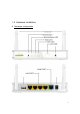
1.2 Hardware Installation A.
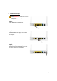
B. Installation Steps Note: DO NOT connect the router to power before performing the installation steps below. Step 1. Plug a USB modem into USB port. Step 2. Insert RJ45 cable into LAN Port on the back panel of the router. Then plug the other end of into computer. Step 3. Plug the power jack into the receptor on the back panel of the router. Then plug the other end into a wall outlet or power strip.
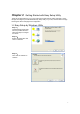
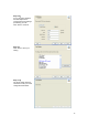
Chapter 2 Getting Started with Easy Setup Utility There are two approaches for you to set up the Wi-Fi Combo Router quickly and easily. One is through executing the provided Windows Easy Setup Utility on your PC, and the other is through browsing the device web pages and configuration. 2.1 Easy Setup by Windows Utility Step 1: Install the Easy Setup Utility from the provided CD then follow the steps to configure the device. Step 2: Select Language then click “Next” to continue.
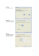
Step 4: Click “Next” to continue. Step 5: Select Wireless Enable, and then click “Next” to continue. Step 6: Enter SSID, Channel and Security options, and then click “Next” to continue.
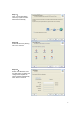
Step 7: Click” Let me select WAN service by myself” to select WAN service manually. Step 8: Select 3G Service by clicking 3G icon to continue. Step 9-1: Select “Auto-Detection” and the Utility will try to detect and configure the required 3G service settings automatically. Click “Next” to continue.
Step 9-2: Or you can select “Manual” and manually fill in the required 3G service settings provided by your ISP. Click “Next” to continue. Step 10: Click “Next” to save your setting. Step 11: The Wi-Fi Combo Router is rebooted to make your entire configuration take effect.
Step 12: Click “Next” to test the Internet connection or you can ignore test. Step 13: Click “Next” to test WAN Networking service. Step 14: Setup is completed.
2.2 Easy Setup by Configuring Web Pages You can also browse web UI to configure the device. Browse to Activate the Setup Wizard Type in the IP Address (http://192.168.123.254) Type in the default password “admin” in the System Password and then click ‘login’ button. Select your language. Select “Wizard” for basic settings with simple way. Press “Next” to start the Setup Wizard.
Configure with the Setup Wizard Step 1: Change System Password. Set up your system password. (Default:admin) Step 2: Select Time Zone. Step 3: Select WAN Type. Choose Auto-Detecting or Manually to set WAN Type.
Step 4: Select Wan Type. If you want to use 3G service as the main internet access, please set the WAN interface as “Wireless WAN” and the WAN type as “3G”. Step 5: 3G Mode. Select Auto-Detection then click “Next” to continue. Step 6: Set up your Wireless Network. Set up your SSID.
Step 7: Setup your Encryption Key here, then click”Next” to continue. Step 8: Apply your Setting. Then click Apply Setting. Step 9: Click Finish to complete it.
Chapter 3 Making Configuration Whenever you want to configure your network or this device, you can access the Configuration Menu by opening the web-browser and typing in the IP Address of the device. The default IP Address is: 192.168.123.254 Enter the default password “admin” in the System Password and then click ‘login’ button. Then, you can browse the “Advanced” configuration pages for configuring this device. 3.
3.1.1. Network Setup 1. LAN IP Address: The local IP address of this device. The computers on your network must use the LAN IP address of this device as their Default Gateway. You can change it if necessary. 2. Subnet Mask: Input your Subnet mask. (All devices in the network must have the same subnet mask.) The default subnet mask is 255.255.255.0. 3. WAN Interface: Select Ethernet WAN or Wireless WAN to continue. 4. WAN Type: WAN connection type of your ISP.
A.
For 3G WAN Networking. The WAN fields may not be necessary for your connection. The information on this page will only be used when your service provider requires you to enter a User Name and Password to connect with the 3G network. Please refer to your documentation or service provider for additional information. 1. Dial-Up Profile: Select “Auto-Detection” or “Manual” to continue.
B. Static IP Address: 1. Activate WWAN for Auto-Failover: With this function enabled, when the Ethernet WAN connection is broken, the device will automatically activate the WWAN connection and keep you connected to internet with the alternative WWAN broadband service. Meanwhile, if the device detected that the Ethernet WAN connection is recovered, your broadband connection will be switched to use the Ethernet WAN service. 2.
C. Dynamic IP Address: 1. Activate WWAN for Auto-Failover: With this function enabled, when the Ethernet WAN connection is broken, the device will automatically activate the WWAN connection and keep you connected to internet with the alternative WWAN broadband service. Meanwhile, if the device detected that the Ethernet WAN connection is recovered, your broadband connection will be switched to use the Ethernet WAN service 2. Host Name: Optional, required by some ISPs, for example, @Home. 3.
D. PPP over Ethernet 1. Activate WWAN for Auto-Failover: With this function enabled, when the Ethernet WAN connection is broken, the device will automatically activate the WWAN connection and keep you connected to internet with the alternative WWAN broadband service. Meanwhile, if the device detected that the Ethernet WAN connection is recovered, your broadband connection will be switched to use the Ethernet WAN service 2. PPPoE Account and Password: The account and password your ISP assigned to you.
3. Connection Control: There are 3 modes to select: Connect-on-demand: The device will link up with ISP when the clients send outgoing packets. Auto Reconnect (Always-on): The device will link with ISP until the connection is established. Manually: The device will not make the link until someone clicks the connect-button in the Status-page. 4. Maximum Idle Time: the amount of time of inactivity before disconnecting your PPPoE session. Set it to zero or enable “Auto-reconnect" to disable this feature. 5.
E. PPTP 1. Activate WWAN for Auto-Failover: With this function enabled, when the Ethernet WAN connection is broken, the device will automatically activate the WWAN connection and keep you connected to internet with the alternative WWAN broadband service. Meanwhile, if the device detected that the Ethernet WAN connection is recovered, your broadband connection will be switched to use the Ethernet WAN service 2.
4. Gateway IP and Server IP Address/Name: The IP address of the PPTP server and designated Gateway provided by your ISP. 5. PPTP Account and Password: The account and password your ISP assigned to you. If you don't want to change the password, keep it blank. 6. Connection ID: Optional. Input the connection ID if your ISP requires it. 7. Maximum Idle Time: the time of no activity to disconnect your PPTP session. Set it to zero or enable “Auto-reconnect” to disable this feature.
F. L2TP 1. Activate WWAN for Auto-Failover: With this function enabled, when the Ethernet WAN connection is broken, the device will automatically activate the WWAN connection and keep you connected to internet with the alternative WWAN broadband service. Meanwhile, if the device detected that the Ethernet WAN connection is recovered, your broadband connection will be switched to use the Ethernet WAN service 2.
5. L2TP Account and Password: The account and password your ISP assigned to you. If you don't want to change the password, keep it blank. 6. Connection ID: Optional. Input the connection ID if your ISP requires it. 7. Maximum Idle Time: The time of no activity to disconnect your L2TP session. Set it to zero or enable “Auto-reconnect” to disable this feature. If Auto-reconnect is enabled, this device will connect with ISP automatically, after system is restarted or connection is dropped. 8.
6. Primary WINS/Secondary WINS: Optional. This feature allows you to assign a WINS Servers 7. Gateway: Optional. Gateway Address would be the IP address of an alternate Gateway. This function enables you to assign another gateway to your PC, when DHCP server offers an IP to your PC. Click on “Save” to store your settings or click “Undo” to give up the changes. Press “Clients List” and the list of DHCP clients will be shown consequently.
3.1.3. Wireless Settings Wireless settings allow you to set the wireless configuration items. 1. Wireless Module: You can enable or disable wireless function. 2. Network ID (SSID): Network ID is used for identifying the Wireless LAN (WLAN). Client stations can roam freely over this device and other Access Points that have the same Network ID. (The factory default setting is “default”) 3.
Open Open system authentication simply consists of two communications. The first is an authentication request by the client that contains the station ID (typically the MAC address). This is followed by an authentication response from the AP/router containing a success or failure message. An example of when a failure may occur is if the client's MAC address is explicitly excluded in the AP/router configuration.
WPA2 WPA2 add uses AES and TKIP for encryption, the others are same the WPA. WPA-PSK/WPA-PSK2 Another encryption options for WPA-PSK-TKIP and WPA-PSK2-AES, the others are same the WPA-PSK. WPA/WPA2 Another encryption options for WPA-TKIP and WPA2-AES, the others are same the WPA. By pressing “WPS Setup”, you can configure and enable the easy setup feature WPS (Wi-Fi Protection Setup) for your wireless network. 1. WPS: You can enable this function by selecting “Enable”.
Press “Wireless Clients List” and the list of wireless clients will be shown consequently. 3.1.4. Change Password You can change the System Password here. We strongly recommend you to change the system password for security reason. Click on “Save” to store your settings or click “Undo” to give up the changes.
3.2 Forwarding Rules 3.2.1 Virtual Server This product’s NAT firewall filters out unrecognized packets to protect your Intranet, so all hosts behind this product are invisible to the outside world. If you wish, you can make some of them accessible by enabling the Virtual Server Mapping. A virtual server is defined as a Service Port, and all requests to this port will be redirected to the computer specified by the Server IP.
Service Port Server IP Enable 21 192.168.123.1 V 80 192.168.123.2 V 1723 192.168.123.6 V Click on “Save” to store your settings or click “Undo” to give up the changes. 3.2.2 Special AP Some applications require multiple connections, like Internet games, Video conferencing, Internet telephony, etc. Because of the firewall function, these applications cannot work with a pure NAT router. The Special Applications feature allows some of these applications to work with this product.
3.2.3 Miscellaneous 1. IP Address of DMZ Host DMZ (Demilitarized Zone) Host is a host without the protection of firewall. It allows a computer to be exposed to unrestricted 2-way communication for Internet games, Video conferencing, Internet telephony and other special applications. 2. UPnP Setting The device supports the UPnP function.
3.3 Security Setting 3.3.1 Packet Filters Packet Filter includes both outbound filter and inbound filter. And they have same way to setting. Packet Filter enables you to control what packets are allowed to pass the router. Outbound filter applies on all outbound packets. However, inbound filter applies on packets that destined to Virtual Servers or DMZ host only. You can select one of the two filtering policies: 1. Allow all to pass except those match the specified rules 2.
You can specify 8 rules for each direction: inbound or outbound. For each rule, you can define the following: • Source IP address • Source port • Destination IP address • Destination port • Protocol: TCP or UDP or both. • Use Rule# For source or destination IP address, you can define a single IP address (4.3.2.1) or a range of IP addresses (4.3.2.1-4.3.2.254). An empty implies all IP addresses. For source or destination port, you can define a single port (80) or a range of ports (1000-1999).
3.3.2 Domain Filters Domain Filter prevents users under this device from accessing specific URLs. 1. Domain Filter: Check if you want to enable Domain Filter. 2. Log DNS Query: Check if you want to log the action when someone accesses the specific URLs. 3. Privilege IP Address Range: Setting a group of hosts and privilege these hosts to access network without restriction. 4. Domain Suffix: A suffix of URL can be restricted, for example, ".com", "xxx.com". 5.
3.3.3 URL Blocking URL Blocking will block LAN computers to connect with pre-define Websites. The major difference between “Domain filter” and “URL Blocking” is Domain filter require user to input suffix (like .com or .org, etc), while URL Blocking require user to input a keyword only. In other words, Domain filter can block specific website, while URL Blocking can block hundreds of websites by simply a keyword. 1. URL Blocking: Check if you want to enable URL Blocking. 2.
3.3.4 MAC Control MAC Address Control allows you to assign different access right for different users and to assign a specific IP address to a certain MAC address. 1. MAC Address Control: Check “Enable” to enable the “MAC Address Control”. All of the settings in this page will take effect only when “Enable” is checked. 2. Connection control: Check "Connection control" to enable the controlling of which wired and wireless clients can connect with this device.
3.3.5 Miscellaneous 1. Administrator Time-out: The time of no activity to logout automatically, you may set it to zero to disable this feature. 2. Remote Administrator Host/Port In general, only Intranet user can browse the built-in web pages to perform administration task. This feature enables you to perform administration task from remote host. If this feature is enabled, only the specified IP address can perform remote administration. If the specified IP address is 0.0.0.
3.4 Advanced Setting 3.4.1 System Log This page support two methods to export system logs to specific destination by means of syslog (UDP) and SMTP(TCP).
1. IP Address for Sys log: Host IP of destination where sys log will be sent to. Check Enable to enable this function. 2. E-mail Alert Enable: Check if you want to enable Email alert (send syslog via email). 3. SMTP Server IP and Port: Input the SMTP server IP and port, which are connected with ':'. If you do not specify port number, the default value is 25. For example, "mail.your_url.com" or "192.168.1.100:26". 4.
3.4.3 QOS Provide different priority to different users or data flows, or guarantee a certain level of performance. 1. QOS Control: Check Enable to enable this function. 2. Bandwidth of Upstream: Set the limitation of upstream bandwidth 3. Local IP : Ports: Define the Local IP address and ports of packets 4. Remote IP : Ports: Define the Remote IP address and ports of packets 5. QoS Priority: This defines the priority level of the current Policy Configuration.
3.4.4 SNMP In brief, SNMP, the Simple Network Management Protocol, is a protocol designed to give a user the capability to remotely manage a computer network by polling and setting terminal values and monitoring network events. 1. Enable SNMP: You must check “Local”, “Remote” or both to enable SNMP function. If “Local” is checked, this device will response request from LAN. If “Remote” is checked, this device will response request from WAN. 2.
3.4.5 Routing If you have more than one routers and subnets, you will need to enable routing table to allow packets to find proper routing path and allow different subnets to communicate with each other. The routing table allows you to determine which physical interface address to use for outgoing IP data grams. 1. Dynamic Routing: Routing Information Protocol (RIP) will exchange information about destinations for computing routes throughout the network.
3.4.6 System Time 1. Time Zone: Select a time zone where this device locates. 2. Auto-Synchronization: Check the “Enable” checkbox to enable this function. Besides, you can select a NTP time server to consult UTC time. 3. Sync with Time Server: Click on the button if you want to set Date and Time by NTP Protocol manually. 4. Sync with my PC: Click on the button if you want to set Date and Time using PC’s Date and Time manually. .
3.4.7 Scheduling You can set the schedule time to decide which service will be turned on or off. 1. Schedule: Check to enable the schedule rule settings. 2. Add New Rule: To create a schedule rule, click the “Add New Rule” button. You can edit the Name of Rule, Policy, and set the schedule time (Week day, Start Time, and End Time). The following example configures “ftp time” as everyday 14:10 to 16:20. Click on “Save” to store your settings or click “Undo” to give up the changes.
3.4.8 IPv6 This device supports several IPv6 applications. You can choose Static IPv6, DHCPv6, PPPoEv6, 6to4, and IPv6 in IPv4 tunnel according to your requirements. 3.4.8.1 Static IPv6 1. IPv6: Disable or enable the IPv6 functions. 2. IPv6 Connection: you can choose Static IPv6 from the list. 3. WAN IPv6 address settings: you can add IPv6 address / subnet prefix length / default Gateway / Primary DNS address and secondary DNS address. 4.
3.4.8.2 DHCPv6 1. IPv6 DNS settings: you may obtain IPv6 DNS automatically or set DNS address manually for Primary DNS address and secondary DNS address. 2. LAN IPv6 address settings: you can add LAN IPv6 address, and IPv6 Link-Local address will be showed automatically. 3. Address auto configuration setting: Disable or enable this auto configuration setting. You may set stateless or stateful( Dynamic IPv6), and also check if need to send Router advertisement messages periodically.
3.4.8.3 PPPoEv6 1. PPPoE settings: you need to type username and password of PPPoE connection. The service name is only required when ISP asks you to input it. MTU is 1492 by default. 2. LAN IPv6 address settings: you can add LAN IPv6 address, and IPv6 Link-Local address will be showed automatically. 3. Address auto configuration setting: Disable or enable this auto configuration setting.
3.4.8.4 6 to 4 1. IPv6 DNS settings: The 6 to 4 address will be showed automatically when WAN gets a public IPv4 address. You may set DNS address manually for Primary DNS address and secondary DNS address. 2. LAN IPv6 address settings: you can add LAN IPv6 address, and IPv6 Link-Local address will be showed automatically. 3. Address auto configuration setting: Disable or enable this auto configuration setting.
3.4.8.5 IPv6 in IPv4 Tunnel 1. IPv6 address in IPv4 Tunnel settings: you may add remote / local IPv4 address and local IPv6 address, and then set DNS address manually for Primary DNS address and secondary DNS address. 2. LAN IPv6 address settings: you can add LAN IPv6 address, and IPv6 Link-Local address will be showed automatically. 3. Address auto configuration setting: Disable or enable this auto configuration setting.
3.5 Tool Box 3.5.1 System Info You can view the System Information and System log, and download/clear the System log, in this page.
3.5.2 Firmware Upgrade You can upgrade firmware by clicking “Upgrade” button. 3.5.3 Backup Setting You can backup your settings by clicking the “Backup Setting” function item and save it as a bin file. Once you want to restore these settings, please click Firmware Upgrade button and use the bin file you saved. 3.5.4 Reset to Default You can also reset this device to factory default settings by clicking the Reset to default function item.
3.5.5 Reboot You can also reboot this device by clicking the Reboot function item. 3.5.6 Miscellaneous 1. Domain Name or IP address for Ping Test: Allow you to configure an IP, and ping the device. You can ping a specific IP to test whether it is alive. Click on “Save” to store your settings or click “Undo” to give up the changes.
Chapter 4 . Troubleshooting This Chapter provides solutions to problems for the installation and operation of the WiFi Combo Router. You can refer to the following if you are having problems. 1 Why can’t I configure the router even the cable is plugged and the LED is lit? Do a Ping test to make sure that the WiFi Combo Router is responding. Note: It is recommended that you use an Ethernet connection to configure it. Go to Start > Run. 1. Type cmd. 2. Press OK. 3.
6. Select Properties to ensure that all drivers are installed properly. 7. Look under Device Status to see if the device is working properly. 8. Click “OK”. 9. 2 What can I do if my Ethernet connection does not work properly? A. Make sure the RJ45 cable connect with the router. B. Ensure that the setting on your Network Interface Card adapter is “Enabled”. C.
G. Why my 3G connection is keep dropping? Please check 3G signal strength from your ISP in your environment is above middle level. 4 Something wrong with the wireless connection? A. Can’t setup a wireless connection? I. Ensure that the SSID and the encryption settings are exactly the same to the Clients. II. Move the WiFi Combo Router and the wireless client into the same room, and then test the wireless connection. III. Disable all security settings such as WEP, and MAC Address Control. IV.
5 What to do if I forgot my encryption key? 1. Go back to advanced setting to set up your Encryption key again. 2. Reset the WiFi Combo Router to default setting 6 How to reset to default? 1. Ensure the WiFi Combo Router is powered on 2. Find the Reset button on the right side 3. Press the Reset button for 8 seconds and then release. 4. After the WiFi Combo Router reboots, it has back to the factory default settings.
Appendix A. Spec Summary Table Hardware & Port Configuration CDW571AM-002 Wireless WAN USB 2.0 for external 3G/4G modem 1 RJ-45 port, 10/100/1000Mbps, Ethernet WAN 1 auto-MDI/MDIX RJ-45 port, 10/100/1000Mbps, Ethernet LAN 4 auto-MDI/MDIX Antenna 1.8 dBi fixed antenna 2 WPS/ WiFi On-Off For WPS connection or WiFi On/Off 1 Reset Button Reset router setting to factory default 1 LED Indication Mobile/ WAN/ WLAN/ LAN1~4 ● Power Jack DC 5V/2A switching power 1 Wireless LAN (WiFi) Standard IEEE 802.
Appendix B. Licensing information This product includes copyrighted third-party software licensed under the terms of the GNU General Public License. Please refer to the GNU General Public License below to check the detailed terms of this license. The following parts of this product are subject to the GNU GPL, and those software packages are copyright by their respective authors. Linux-2.4.28 system kernel busybox_1_00_rc2 bridge-utils 0.9.5 dhcpcd-1.3 ISC DHCP V2 P5 util-linux 2.
GNU GENERAL PUBLIC LICENSE Version 2, June 1991 Copyright (C) 1989, 1991 Free Software Foundation, Inc. 59 Temple Place, Suite 330, Boston, MA 02111-1307 USA Everyone is permitted to copy and distribute verbatim copies of this license document, but changing it is not allowed. Preamble The licenses for most software are designed to take away your freedom to share and change it.
GNU GENERAL PUBLIC LICENSE TERMS AND CONDITIONS FOR COPYING, DISTRIBUTION AND MODIFICATION 0. This License applies to any program or other work which contains a notice placed by the copyright holder saying it may be distributed under the terms of this General Public License.
a) Accompany it with the complete corresponding machine-readable source code, which must be distributed under the terms of Sections 1 and 2 above on a medium customarily used for software interchange; or, b) Accompany it with a written offer, valid for at least three years, to give any third party, for a charge no more than your cost of physically performing source distribution, a complete machine-readable copy of the corresponding source code, to be distributed under the terms of Sections 1 and 2 above on
integrity of the free software distribution system, which is implemented by public license practices. Many people have made generous contributions to the wide range of software distributed through that system in reliance on consistent application of that system; it is up to the author/donor to decide if he or she is willing to distribute software through any other system and a licensee cannot impose that choice.