FOXCONN 911400100-07A-G 911400200-07A-G WAVE User’s Manual Copyright The contents of this publication may not be reproduced in any part or as a whole, stored, transcribed in an information retrieval system, translated into any language, or transmitted in any form or by any means, mechanical, magnetic, electronic, optical, photocopying, manual, or otherwise, without the prior written permission.
Table of Contents Chapter 1 Introduction .............................................................................. 3 Functions and Features ........................................................................ 3 Packing List ......................................................................................... 5 Chapter 2 Hardware Installation ............................................................... 6 2.1 Panel Layout ........................................................................
C Chhaapptteerr 11 IInnttrroodduuccttiioonn Congratulations on your purchase of this outstanding Wireless Broadband Router. This product is specifically designed for Small Office and Home Office needs. It provides a complete SOHO solution for Internet surfing, and is easy to configure and operate even for non-technical users. Instructions for installing and configuring this product can be found in this manual.
Wireless functions z High speed for wireless LAN connection Up to 54Mbps data rate by incorporating Orthogonal Frequency Division Multiplexing (OFDM). z Roaming Provides seamless roaming within the IEEE 802.11b (11M) and IEEE 802.11g (54M) WLAN infrastructure. z IEEE 802.11b compatible (11M) Allowing inter-operation among multiple vendors. z IEEE 802.11g compatible (54M) Allowing inter-operation among multiple vendors. z Auto fallback 54M, 48M, 36M, 24M, 18M, 12M, 6M data rate with auto fallback in 802.
When this feature is enabled, the router will detect and log the DoS attack comes from the Internet. Advanced functions z System time Supported Allow you to synchronize system time with network time server. z E-mail Alert Supported The router can send its info by mail. z Dynamic dns Supported At present,the router has 4 ddns.dyndns,No-IP,TZO.com and dhs.org. z SNMP Supported The router supports basic SNMP function. z Routing Table Supported Now, the router supports static routing.
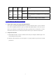
C Chhaapptteerr 22 H Haarrddw waarree IInnssttaallllaattiioonn 2.1 Panel Layout Figure 2-2 Rear Panel LED: LED Status WAN WLAN Function System status WAN port activity Wireless activity Color Status Green Blinking Green On The WAN port is linked. Blinking The WAN port is sending or receiving data. Blinking Sending or receiving data via wireless Green Description 6 Status is flashed once per second to indicate system is alive.
Link. 1~2 Link status Green LAN port. Blinking Speed 10/100 An active station is connected to the corresponding On Data Rate Green The corresponding LAN port is sending or receiving data. Data is transmitting in 100Mbps on the corresponding On LAN port. Reset To reset system settings to factory defaults 2.2 Procedure for Hardware Installation 2.
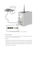
Figure 2-3 Setup of LAN and WAN connections for this product. 3. Setup WAN connection Prepare an Ethernet cable for connecting this product to your cable/xDSL modem or Ethernet backbone. Figure 2-3 illustrates the WAN connection. 4. Power on Connecting the power cord to power inlet and turning the power switch on, this product will automatically enter the self-test phase.
C Chhaapptteerr 33 N waarree IInnssttaallllaattiioonn Neettw woorrkk SSeettttiinnggss aanndd SSooffttw To use this product correctly, you have to properly configure the network settings of your computers and install the attached setup program into your MS Windows platform (Windows 95/98/NT/2000). 3.1 Make Correct Network Settings of Your Computer The default IP address of this product is 192.168.123.254, and the default subnet mask is 255.255.255.0.
C Chhaapptteerr 44 C Roouutteerr Coonnffiigguurriinngg W Wiirreelleessss B Brrooaaddbbaanndd R This product provides Web based configuration scheme, that is, configuring by your Web browser, such as Netscape Communicator or Internet Explorer. This approach can be adopted in any MS Windows, Macintosh or UNIX based platforms.
4.1 Login to Configure from Wizard Activate your browser, and disable the proxy or add the IP address of this product into the exceptions. Then, type this product’s IP address in the Location (for Netscape) or Address (for IE) field and press ENTER. For example: http://192.168.123.254. After the connection is established, you will see the web user interface of this product. There are two appearances of web user interface: for general users and for system administrator.
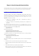
If the user finishes those steps and the router shows as below. It means that customers can enjoy Internet.
4.2 Status This option provides the function for observing this product’s working status: A. WAN Port Status. If the WAN port is assigned a dynamic IP, there may appear a “Renew” or “Release” button on the Sidenote column. You can click this button to renew or release IP manually. B.
4.
4.4.
This option is primary to enable this product to work properly. The setting items and the web appearance depend on the WAN type. Choose correct WAN type before you start. 1. LAN IP Address: the local IP address of this device. The computers on your network must use the LAN IP address of your product as their Default Gateway. You can change it if necessary. 2. WAN Type: WAN connection type of your ISP. You can click Change button to choose a correct one from the following four options: A.
1. Host Name: optional. Required by some ISPs, for example, @Home. 2. Renew IP Forever: this feature enables this product to renew your IP address automatically when the lease time is expiring-- even when the system is idle. 4.4.1.3 Dynamic IP Address with Road Runner Session Management.(e.g. Telstra BigPond) 1. LAN IP Address is the IP address of this product. It must be the default gateway of your computers. 2. WAN Type is Dynamic IP Address. If the WAN type is not correct, change it! 3.
1. My IP Address and My Subnet Mask: the private IP address and subnet mask your ISP assigned to you. 2. Server IP Address: the IP address of the PPTP server. 3. PPTP Account and Password: the account and password your ISP assigned to you. If you don't want to change the password, keep it empty. 3. Connection ID: optional. Input the connection ID if your ISP requires it. 4. Maximum Idle Time: the time of no activity to disconnect your PPTP session.
4.4.1.6 L2TP First,Please check your ISP assigned and Select Static IP Address or Dynamic IP Address. For example:Use Static 1. My IP Address and My Subnet Mask: the private IP address and subnet mask your ISP assigned to you. 2. Server IP Address: the IP address of the PPTP server. 3. PPTP Account and Password: the account and password your ISP assigned to you. If you don't want to change the password, keep it empty. 3. Connection ID: optional. Input the connection ID if your ISP requires it. 4.
connect to ISP automatically, after system is restarted or connection is dropped. 6. Connection Control:There are 3 modes to select: Connect-on-demand:The device will link up with ISP when the clients send outgoing packets. Auto-Reconnect(Always-on):The device will link upw with ISP until the connection is established. Manually:The device will not make the link until someone clicks the connect-button in the Staus-page.
4.4.1.7 Virtual Computers(Only for Static and dynamic IP address Wan type) Virtual Computer enables you to use the original NAT feature, and allows you to setup the one-to-one mapping of multiple global IP address and local IP address. • Global IP: Enter the global IP address assigned by your ISP. • Local IP: Enter the local IP address of your LAN PC corresponding to the global IP address. • Enable: Check this item to enable the Virtual Computer feature.
4.4.2 DHCP Server Press “More>>” The settings of a TCP/IP environment include host IP, Subnet Mask, Gateway, and DNS configurations. It is not easy to manually configure all the computers and devices in your network. Fortunately, DHCP Server provides a rather simple approach to handle all these settings. This product supports the function of DHCP server.
4.4.3 Wireless Setting, 802.1X setting and WDS Wireless settings allow you to set the wireless configuration items. Wireless : The user can enable or disalbe wireless function. Network ID (SSID): Network ID is used for identifying the Wireless LAN (WLAN). Client stations can roam freely over this product and other Access Points that have the same Network ID.
it is transferred from one station to another. There are several security types to use: WEP : When you enable the 128 or 64 bit WEP key security, please select one WEP key to be used and input 26 or 10 hexadecimal (0, 1, 2…8, 9, A, B…F) digits. 802.1X Check Box was used to switch the function of the 802.1X. When the 802.1X function is enabled, the Wireless user must authenticate to this router first to use the Network service. RADIUS Server IP address or the 802.1X server’s domain-name.
WPA-PSK 1. Select Encryption and Pre-share Key Mode If you select HEX, you have to fill in 64 hexadecimal (0, 1, 2…8, 9, A, B…F) digits If ASCII, the length of pre-share key is from 8 to 63. 2. Fill in the key, Ex 12345678 WPA Check Box was used to switch the function of the WPA. When the WPA function is enabled, the Wireless user must authenticate to this router first to use the Network service. RADIUS Server IP address or the 802.1X server’s domain-name.
WPA2-PSK(AES) 1. Select Pre-share Key Mode If you select HEX, you have to fill in 64 hexadecimal (0, 1, 2…8, 9, A, B…F) digits If ASCII, the length of Pre-share key is from 8 to 63. 2.
WPA2(AES) Check Box was used to switch the function of the WPA. When the WPA function is enabled, the Wireless user must authenticate to this router first to use the Network service. RADIUS Server IP address or the 802.1X server’s domain-name. Select RADIUS Shared Key If you select HEX, you have to fill in 64 hexadecimal (0, 1, 2…8, 9, A, B…F) digits If ASCII, the length of Pre-share key is from 8 to 63. Key value shared by the RADIUS server and this router.
WPA-PSK /WPA2-PSK The router will detect automatically which Security type the client uses to encrypt. 1. Select Pre-share Key Mode If you select HEX, you have to fill in 64 hexadecimal (0, 1, 2…8, 9, A, B…F) digits If ASCII, the length of Pre-share key is from 8 to 63. 2.
WPA/WPA2 Check Box was used to switch the function of the WPA. When the WPA function is enabled, the Wireless user must authenticate to this router first to use the Network service. RADIUS Server The router will detect automatically which Security type(Wpa-psk version 1 or 2) the client uses to encrypt. IP address or the 802.1X server’s domain-name.
WDS(Wireless Distribution System) WDS operation as defined by the IEEE802.11 standard has been made available. Using WDS it is possible to wirelessly connect Access Points, and in doing so extend a wired infrastructure to locations where cabling is not possible or inefficient to implement.
4.4.4 Change Password You can change Password here. We strongly recommend you to change the system password for security reason.
4.
4.5.1 Virtual Server This product’s NAT firewall filters out unrecognized packets to protect your Intranet, so all hosts behind this product are invisible to the outside world. If you wish, you can make some of them accessible by enabling the Virtual Server Mapping. A virtual server is defined as a Service Port, and all requests to this port will be redirected to the computer specified by the Server IP. Virtual Server can work with Scheduling Rules, and give user more flexibility on Access control.
4.5.2 Special AP Some applications require multiple connections, like Internet games, Video conferencing, Internet telephony, etc. Because of the firewall function, these applications cannot work with a pure NAT router. The Special Applications feature allows some of these applications to work with this product. If the mechanism of Special Applications fails to make an application work, try setting your computer as the DMZ host instead. 1. Trigger: the outbound port number issued by the application.. 2.
4.5.3 Miscellaneous Items IP Address of DMZ Host DMZ (DeMilitarized Zone) Host is a host without the protection of firewall. It allows a computer to be exposed to unrestricted 2-way communication for Internet games, Video conferencing, Internet telephony and other special applications. NOTE: This feature should be used only when needed. Non-standard FTP port You have to configure this item if you want to access an FTP server whose port number is not 21. This setting will be lost after rebooting.
4.
4.6.1 Packet Filter Packet Filter enables you to control what packets are allowed to pass the router. Outbound filter applies on all outbound packets. However, Inbound filter applies on packets that destined to Virtual Servers or DMZ host only. You can select one of the two filtering policies: 1. Allow all to pass except those match the specified rules 2. Deny all to pass except those match the specified rules You can specify 8 rules for each direction: inbound or outbound.
For source or destination IP address, you can define a single IP address (4.3.2.1) or a range of IP addresses (4.3.2.1-4.3.2.254). An empty implies all IP addresses. For source or destination port, you can define a single port (80) or a range of ports (1000-1999). Add prefix "T" or "U" to specify TCP or UDP protocol. For example, T80, U53, U2000-2999. No prefix indicates both TCP and UDP are defined. An empty implies all port addresses.
(1.2.3.100-1.2.3.149) They are allow to send mail (port 25), receive mail (port 110), and browse the Internet (port 80) (1.2.3.10-1.2.3.20) They can do everything (block nothing) Others are all blocked. Example 2: (1.2.3.100-1.2.3.119) They can do everything except read net news (port 119) and transfer files via FTP (port 21) Others are all allowed. After Inbound Packet Filter setting is configured, click the save button.
Example 1: (192.168.123.100-192.168.123.149) They are allowed to send mail (port 25), receive mail (port 110), and browse Internet (port 80); port 53 (DNS) is necessary to resolve the domain name. (192.168.123.10-192.168.123.20) They can do everything (block nothing) Others are all blocked.
Example 2: (192.168.123.100-192.168.123.119) They can do everything except read net news (port 119) and transfer files via FTP (port 21) Others are allowed After Outbound Packet Filter setting is configured, click the save button.
4.6.2 Domain Filter Domain Filter Let you prevent users under this device from accessing specific URLs. Domain Filter Enable Check if you want to enable Domain Filter. Log DNS Query Check if you want to log the action when someone accesses the specific URLs. Privilege IP Addresses Range Setting a group of hosts and privilege these hosts to access network without restriction. Domain Suffix A suffix of URL to be restricted. For example, ".com", "xxx.com".
Example: In this example: 1. URL include “www.msn.com” will be blocked, and the action will be record in log-file. 2. URL include “www.sina.com” will not be blocked, but the action will be record in log-file. 3. URL include “www.google.com” will be blocked, but the action will not be record in log-file. 4. IP address X.X.X.1~ X.X.X.20 can access network without restriction.
4.6.3 URL Blocking URL Blocking will block LAN computers to connect to pre-defined Websites. The major difference between “Domain filter” and “URL Blocking” is Domain filter require user to input suffix (like .com or .org, etc), while URL Blocking require user to input a keyword only. In other words, Domain filter can block specific website, while URL Blocking can block hundreds of websites by simply a keyword. URL Blocking Enable Checked if you want to enable URL Blocking.
In this example: 1. URL include “msn” will be blocked, and the action will be record in log-file. 2. URL include “sina” will be blocked, but the action will be record in log-file 3. URL include “cnnsi” will not be blocked, but the action will be record in log-file. 4.
4.6.4 MAC Address Control MAC Address Control allows you to assign different access right for different users and to assign a specific IP address to a certain MAC address. MAC Address Control Check “Enable” to enable the “MAC Address Control”. All of the settings in this page will take effect only when “Enable” is checked. Connection control Check "Connection control" to enable the controlling of which wired and wireless clients can connect to this device.
via this device. Choose "allow" or "deny" to allow or deny the clients, whose MAC addresses are not in the "Control table", to associate to the wireless LAN. Control table "Control table" is the table at the bottom of the "MAC Address Control" page. Each row of this table indicates the MAC address and the expected IP address mapping of a client. There are four columns in this table: MAC Address MAC address indicates a specific client. IP Address Expected IP address of the corresponding client.
Example: In this scenario, there are three clients listed in the Control Table. Clients 1 and 2 are wireless, and client 3 is wired. 1.The "MAC Address Control" function is enabled. 2."Connection control" is enabled, and all of the wired and wireless clients not listed in the "Control table" are "allowed" to connect to this device. 3."Association control" is enabled, and all of the wireless clients not listed in the "Control table" are "denied" to associate to the wireless LAN. 4.
5.Clients 2 and 3 and other wired clients with a MAC address unspecified in the Control table are all allowed to connect to this device. But client 1 is denied to connect to this device. 6.Clients 1 and 2 are allowed to associate to the wireless LAN, but a wireless client with a MAC address not specified in the Control table is denied to associate to the wireless LAN. Client 3 is a wired client and so is not affected by Association control. 4.6.
IP address, port address, ACK, SEQ number and so on. And the router will check every incoming packet to detect if this packet is valid. DoS Attack Detection When this feature is enabled, the router will detect and log the DoS attack comes from the Internet. Currently, the router can detect the following DoS attack: SYN Attack, WinNuke, Port Scan, Ping of Death, Land Attack etc. 4.