User’s Manual Copyright The contents of this publication may not be reproduced in any part or as a whole, stored, transcribed in an information retrieval system, translated into any language, or transmitted in any form or by any means, mechanical, magnetic, electronic, optical, photocopying, manual, or otherwise, without the prior written permission. Trademarks All products, company, brand names are trademarks or registered trademarks of their respective companies.
Table of Contents Chapter 1 Introduction .............................................................................. 3 Functions and Features ........................................................................ 3 Packing List ......................................................................................... 5 Chapter 2 Hardware Installation ............................................................... 6 2.1 Panel Layout ........................................................................
C Chhaapptteerr 11 IInnttrroodduuccttiioonn Congratulations on your purchase of this outstanding Wireless Broadband Router. This product is specifically designed for Small Office and Home Office needs. It provides a complete SOHO solution for Internet surfing, and is easy to configure and operate even for non-technical users. Instructions for installing and configuring this product can be found in this manual.
z Statistics of WAN Supported Enables you to monitor inbound and outbound packets Wireless functions z High speed for wireless LAN connection Up to 54Mbps data rate by incorporating Orthogonal Frequency Division Multiplexing (OFDM). z Roaming Provides seamless roaming within the IEEE 802.11b (11M) and IEEE 802.11g (54M) WLAN infrastructure. z IEEE 802.11b compatible (11M) Allowing inter-operation among multiple vendors. z IEEE 802.11g compatible (54M) Allowing inter-operation among multiple vendors.
use the Network service z SPI Mode Supported When SPI Mode is enabled, the router will check every incoming packet to detect if this packet is valid. z DoS Attack Detection Supported When this feature is enabled, the router will detect and log the DoS attack comes from the Internet. Advanced functions z System time Supported Allow you to synchronize system time with network time server. z E-mail Alert Supported The router can send its info by mail. z Dynamic dns Supported At present,the router has 3 ddns.
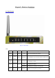
C Chhaapptteerr 22 H Haarrddw waarree IInnssttaallllaattiioonn 2.1 Panel Layout 2.1.1. Front Panel Figure 2-1 Front Panel LED: LED POWER M1 USB WAN Wireless Function Power indication System status USB port activity WAN port activity Wireless activity Color Status Description Green On Green Blinking Green On The USB port is linked. On The WAN port is linked. Green Green Power is being applied to this product. M1 is flashed once per second to indicate system is alive.
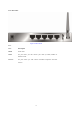
Link/Act. 1~4 10/100 Link status Green An active station is connected to the corresponding LAN On port. Blinking Data Rate Green RESET Button The corresponding LAN port is sending or receiving data. Data is transmitting in 100Mbps on the corresponding On LAN port.
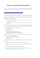
2.1.2. Rear Panel Figure 2-2 Rear Panel Ports: Port Description PWR Power inlet WAN the port where you will connect your cable (or DSL) modem or Ethernet router. Port 1-4 the ports where you will connect networked computers and other devices.
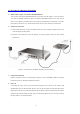
2.2 Procedure for Hardware Installation 2. Decide where to place your Wireless Broadband Router You can place your Wireless Broadband Router on a desk or other flat surface, or you can mount it on a wall. For optimal performance, place your Wireless Broadband Router in the center of your office (or your home) in a location that is away from any potential source of interference, such as a metal wall or microwave oven. This location must be close to power and network connection. 2. Setup LAN connection a.
C Chhaapptteerr 33 N Neettw woorrkk SSeettttiinnggss aanndd SSooffttw waarree IInnssttaallllaattiioonn To use this product correctly, you have to properly configure the network settings of your computers and install the attached setup program into your MS Windows platform (Windows 95/98/NT/2000). 3.1 Make Correct Network Settings of Your Computer The default IP address of this product is 192.168.123.254, and the default subnet mask is 255.255.255.0.
C Chhaapptteerr 44 C Coonnffiigguurriinngg W Wiirreelleessss B Brrooaaddbbaanndd R Roouutteerr This product provides Web based configuration scheme, that is, configuring by your Web browser, such as Netscape Communicator or Internet Explorer. This approach can be adopted in any MS Windows, Macintosh or UNIX based platforms.
4.1 Start-up and Log in Activate your browser, and disable the proxy or add the IP address of this product into the exceptions. Then, type this product’s IP address in the Location (for Netscape) or Address (for IE) field and press ENTER. For example: http://192.168.123.254. After the connection is established, you will see the web user interface of this product. There are two appearances of web user interface: for general users and for system administrator.
4.2 Status This option provides the function for observing this product’s working status: A. WAN Port Status. If the WAN port is assigned a dynamic IP, there may appear a “Renew” or “Release” button on the Sidenote column. You can click this button to renew or release IP manually. B.
4.3 Wizard Setup Wizard will guide you through a basic configuration procedure step by step.Press ”Next >” Setup Wizard - Select WAN Type: For detail settings, please refer to 4.4.1 primary setup.
4.4 Basic Setting 4.4.
Press “Change” This option is primary to enable this product to work properly. The setting items and the web appearance depend on the WAN type. Choose correct WAN type before you start. 1. LAN IP Address: the local IP address of this device. The computers on your network must use the LAN IP address of your product as their Default Gateway. You can change it if necessary. 2. WAN Type: WAN connection type of your ISP. You can click Change button to choose a correct one from the following four options: A.
2. Renew IP Forever: this feature enables this product to renew your IP address automatically when the lease time is expiring-- even when the system is idle. 4.4.1.3 Dynamic IP Address with Road Runner Session Management.(e.g. Telstra BigPond) 1. LAN IP Address is the IP address of this product. It must be the default gateway of your computers. 2. WAN Type is Dynamic IP Address. If the WAN type is not correct, change it! 3. Host Name: optional. Required by some ISPs, e.g. @Home. 4.
3. PPTP Account and Password: the account and password your ISP assigned to you. If you don't want to change the password, keep it empty. 3. Connection ID: optional. Input the connection ID if your ISP requires it. 4. Maximum Idle Time: the time of no activity to disconnect your PPTP session. Set it to zero or enable Auto-reconnect to disable this feature. If Auto-reconnect is enabled, this product will connect to ISP automatically, after system is restarted or connection is dropped. 5.
4.4.1.6 L2TP First,Please check your ISP assigned and Select Static IP Address or Dynamic IP Address. For example:Use Static 1. My IP Address and My Subnet Mask: the private IP address and subnet mask your ISP assigned to you. 2. Server IP Address: the IP address of the PPTP server. 3. PPTP Account and Password: the account and password your ISP assigned to you. If you don't want to change the password, keep it empty. 3. Connection ID: optional. Input the connection ID if your ISP requires it. 4.
4.4.1.
Virtual Computer enables you to use the original NAT feature, and allows you to setup the one-to-one mapping of multiple global IP address and local IP address. • Global IP: Enter the global IP address assigned by your ISP. • Local IP: Enter the local IP address of your LAN PC corresponding to the global IP address. • Enable: Check this item to enable the Virtual Computer feature. 4.4.
5. Primary WINS/Secondary WINS: This feature allows you to assign WINS Servers 6. Gateway: The Gateway Address would be the IP address of an alternate Gateway. This function enables you to assign another gateway to your PC, when DHCP server offers an IP to your PC. 4.4.3 Wireless Setting, and 802.1X setting Wireless settings allow you to set the wireless configuration items. 1. Network ID (SSID): Network ID is used for identifying the Wireless LAN (WLAN).
6. 802.1X Setting 802.1X Check Box was used to switch the function of the 802.1X. When the 802.1X function is enabled, the Wireless user must authenticate to this router first to use the Network service. RADIUS Server IP address or the 802.1X server’s domain-name. RADIUS Shared Key Key value shared by the RADIUS server and this router. This key value is consistent with the key value in the RADIUS server. WPA-PSK 1.
WPA Check Box was used to switch the function of the WPA. When the WPA function is enabled, the Wireless user must authenticate to this router first to use the Network service. RADIUS Server IP address or the 802.1X server’s domain-name. RADIUS Shared Key Key value shared by the RADIUS server and this router. This key value is consistent with the key value in the RADIUS server.
4.4.4 Change Password You can change Password here. We strongly recommend you to change the system password for security reason.
4.5 Forwarding Rules 4.5.
This product’s NAT firewall filters out unrecognized packets to protect your Intranet, so all hosts behind this product are invisible to the outside world. If you wish, you can make some of them accessible by enabling the Virtual Server Mapping. A virtual server is defined as a Service Port, and all requests to this port will be redirected to the computer specified by the Server IP. Virtual Server can work with Scheduling Rules, and give user more flexibility on Access control.
4.5.2 Special AP Some applications require multiple connections, like Internet games, Video conferencing, Internet telephony, etc. Because of the firewall function, these applications cannot work with a pure NAT router. The Special Applications feature allows some of these applications to work with this product. If the mechanism of Special Applications fails to make an application work, try setting your computer as the DMZ host instead. 1. Trigger: the outbound port number issued by the application.. 2.
4.5.3 Miscellaneous Items IP Address of DMZ Host DMZ (DeMilitarized Zone) Host is a host without the protection of firewall. It allows a computer to be exposed to unrestricted 2-way communication for Internet games, Video conferencing, Internet telephony and other special applications. NOTE: This feature should be used only when needed. Non-standard FTP port You have to configure this item if you want to access an FTP server whose port number is not 21. This setting will be lost after rebooting.
4.
4.6.1 Packet Filter Packet Filter enables you to control what packets are allowed to pass the router. Outbound filter applies on all outbound packets. However, Inbound filter applies on packets that destined to Virtual Servers or DMZ host only. You can select one of the two filtering policies: 1. Allow all to pass except those match the specified rules 2. Deny all to pass except those match the specified rules You can specify 8 rules for each direction: inbound or outbound.
addresses (4.3.2.1-4.3.2.254). An empty implies all IP addresses. For source or destination port, you can define a single port (80) or a range of ports (1000-1999). Add prefix "T" or "U" to specify TCP or UDP protocol. For example, T80, U53, U2000-2999. No prefix indicates both TCP and UDP are defined. An empty implies all port addresses. Packet Filter can work with Scheduling Rules, and give user more flexibility on Access control. For Detail, please refer to Scheduling Rule.
(1.2.3.10-1.2.3.20) They can do everything (block nothing) Others are all blocked. Example 2: (1.2.3.100-1.2.3.119) They can do everything except read net news (port 119) and transfer files via FTP (port 21) Others are all allowed. After Inbound Packet Filter setting is configured, click the save button. Outbound Filter: To enable Outbound Packet Filter click the check box next to Enable in the Outbound Packet Filter field.
Example 1: (192.168.123.100-192.168.123.149) They are allowed to send mail (port 25), receive mail (port 110), and browse Internet (port 80); port 53 (DNS) is necessary to resolve the domain name. (192.168.123.10-192.168.123.20) They can do everything (block nothing) Others are all blocked.
Example 2: (192.168.123.100-192.168.123.119) They can do everything except read net news (port 119) and transfer files via FTP (port 21) Others are allowed After Outbound Packet Filter setting is configured, click the save button.
4.6.2 Domain Filter Domain Filter Let you prevent users under this device from accessing specific URLs. Domain Filter Enable Check if you want to enable Domain Filter. Log DNS Query Check if you want to log the action when someone accesses the specific URLs. Privilege IP Addresses Range Setting a group of hosts and privilege these hosts to access network without restriction. Domain Suffix A suffix of URL to be restricted. For example, ".com", "xxx.com".
Example: In this example: 1. URL include “www.msn.com” will be blocked, and the action will be record in log-file. 2. URL include “www.sina.com” will not be blocked, but the action will be record in log-file. 3. URL include “www.google.com” will be blocked, but the action will not be record in log-file. 4. IP address X.X.X.1~ X.X.X.20 can access network without restriction.
4.6.3 URL Blocking URL Blocking will block LAN computers to connect to pre-defined Websites. The major difference between “Domain filter” and “URL Blocking” is Domain filter require user to input suffix (like .com or .org, etc), while URL Blocking require user to input a keyword only. In other words, Domain filter can block specific website, while URL Blocking can block hundreds of websites by simply a keyword. URL Blocking Enable Checked if you want to enable URL Blocking.
In this example: 1. URL include “msn” will be blocked, and the action will be record in log-file. 2. URL include “sina” will be blocked, but the action will be record in log-file 3. URL include “cnnsi” will not be blocked, but the action will be record in log-file. 4.
4.6.4 MAC Address Control MAC Address Control allows you to assign different access right for different users and to assign a specific IP address to a certain MAC address. MAC Address Control Check “Enable” to enable the “MAC Address Control”. All of the settings in this page will take effect only when “Enable” is checked. Connection control Check "Connection control" to enable the controlling of which wired and wireless clients can connect to this device.
associate to the wireless LAN. Control table "Control table" is the table at the bottom of the "MAC Address Control" page. Each row of this table indicates the MAC address and the expected IP address mapping of a client. There are four columns in this table: MAC Address MAC address indicates a specific client. IP Address Expected IP address of the corresponding client. Keep it empty if you don't care its IP address.
4.6.5 Miscellaneous Items Remote Administrator Host/Port In general, only Intranet user can browse the built-in web pages to perform administration task. This feature enables you to perform administration task from remote host. If this feature is enabled, only the specified IP address can perform remote administration. If the specified IP address is 0.0.0.0, any host can connect to this product to perform administration task.
Currently, the router can detect the following DoS attack: SYN Attack, WinNuke, Port Scan, Ping of Death, Land Attack etc.
4.
4.7.1 System Time Get Date and Time by NTP Protocol Selected if you want to Get Date and Time by NTP Protocol. Time Server Select a NTP time server to consult UTC time Time Zone Select a time zone where this device locates. Set Date and Time manually Selected if you want to Set Date and Time manually. Set Date and Time manually Selected if you want to Set Date and Time manually. Function of Buttons Sync Now: Synchronize system time with network time server Daylight Saving:Set up where the location is.
4.7.2 System Log This page support two methods to export system logs to specific destination by means of syslog(UDP) and SMTP(TCP). The items you have to setup including: IP Address for Syslog Host IP of destination where syslogs will be sent to. Check Enable to enable this function. E-mail Alert Enable Check if you want to enable Email alert (send syslog via email). SMTP Server IP and Port Input the SMTP server IP and port, which are concated with ':'.
4.7.3 Dynamic DNS To host your server on a changing IP address, you have to use dynamic domain name service (DDNS). So that anyone wishing to reach your host only needs to know the name of it. Dynamic DNS will map the name of your host to your current IP address, which changes each time you connect your Internet service provider. Before you enable Dynamic DNS, you need to register an account on one of these Dynamic DNS servers that we list in provider field.
Password/Key You will get this information when you register an account on a Dynamic DNS server. Example: After Dynamic DNS setting is configured, click the save button.
4.7.4 SNMP Setting In brief, SNMP, the Simple Network Management Protocol, is a protocol designed to give a user the capability to remotely manage a computer network by polling and setting terminal values and monitoring network events. Enable SNMP You must check either Local or Remote or both to enable SNMP function. If Local is checked, this device will response request from LAN. If Remote is checked, this device will response request from WAN.