APR.
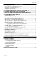
APR. 25, 2003 TABLE OF CONTENTS: INSTALLATION DIAGRAM …………….…………………………………………….……………………………. 3 H1: 5 PIN WIRE HARNESS …..……………………………………………………….………………..…………. 4 H1/1 Red / White wire – Parking Light Relay Power Input ……………………….……..…...….….………..4 H1/2 White wire – Parking Light Relay Output ……………………………….……..………….….………..…5 H1/3 Black wire – System Ground …………………………………………….……..………………...……… 5 H1/4 Brown wire – Siren Drive Output ………..……………………………….……..…………..…………… 5 H1/5 Red wire – System Power ………………….………………………….
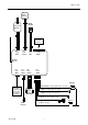
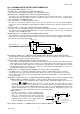
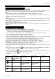
APR. 25, 2003 INSTALLATION DIAGRAM Optional Pager (Knock) Sensor VALET SWITCH Transmitter Antenna H8 14 Pin White Connector H6 3 Pin Brown H5 4 Pin Black H7 2 Pin Blue H8 14 Pin White Receiver Antenna H3 2 Pin White H4 3 Pin White H2 4 Pin Orange H1 6 Pin White 10A Fuse 1. Red / White: Parking Light Relay Power input H4 3 Pin White Connector for Door Lock & Door unlock Connection Dual Zone Shock Sensor 2. White: Parking Light Relay Output 3. Black: Ground to Vehicle Frame 4.
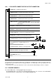
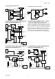
APR. 25, 2003 #H8. 14 PIN WHITE CONNECTOR FOR OUTPUT CONNECTION 14. White Wire: (-) 200mA Dome light Output 13. Black/Violet Wire: (-) 200mA Channel 6 Timer Control Output 12. White/Red Wire: (-) 200mA Factory Security Disarm Output 11. Black/Red Wire: (-) 200mA Channel 5 Timer Control Output 10. Black/Green Wire: (-) 200mA Programmable Output Channel 4 Timer Control Output (Factory Default Setting) Or Horn Output 9. Gray Wire: (-) 200mA Channel 3 Timer Control Output 8.
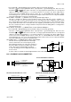
APR. 25, 2003 If the vehicle you are working on has +12volt switched parking light, you don’t need connect this wire. This wire already connected to +12 volt. If the vehicle’s parking light are ground switched, cut the RED/WHITE wire, connect the RED/WHITE wire to chassis ground. H1/2 White wire – Parking Light Relay Output (10A power output) – (See Feature II – 4 Programming) Connect the WHITE wire to the parking light wire coming from the headlight switch.
APR. 25, 2003 H8: 14-PIN MINI WHITE OUTPUT WIRE CONNECTOR: H8/1. BLACK/WHITE WIRE – No Use -H8/2 Blue wire – Ground Instant Trigger Input (Zone 2) – This wire is the ground trigger input wire for hood/trunk pin switches. H8/3 Green wire – Negative Door Switch Sensing Input (Zone 3) – This wire is the ground trigger input wire for negative door pin switch. This wire is connection for "grounding" type factory door pins locate the "common wire" that connects the door pin switches.
APR. 25, 2003 (See Feature IV – 3 Programming) (Factory default setting on momentary grounded) This wire is built-in user-programmable timer output provides a ground through this wire. Press the button at the same time. You may program the built-in timer to send a ground and transmitter signal for any time interval between 1 second and 2 minutes. For instance, this timer output may be used to turn on the headlight with the remote control.
APR.
APR. 25, 2003 ROGRAMMING A. PROGRAMMING TRANSMITTER: PROGRAMMING THE REMOTE TRANSMITTER Note: This mode will only retain the last 4 remote transmitters programmed. If the transmitter memory is exceeded, the security system will start deleting transmitters from memory in chronological order. Enter: 1. Turn the Ignition 'switch ‘OFF/ON’ 3 TIMES and stay in ON position. Within 15 seconds. 2. Push the Valet switch 3 times and hold it until a long chirp is hearing then release the valet switch.
APR. 25, 2003 Exit: Turn Ignition to 'ON' position, or leave it for 15 seconds. A 3 long chirps & 3 parking light flashes to confirm exit. 3 / 30 seconds Delay Door Ajar Error Chirp: This feature controls the error chirp that is generated if the system is armed with the door trigger active. This useful in vehicles that has a long dome light delay after the door has been closed. If the system is armed before the dome light has turned off, the security system will generate the door trigger error chirp.
APR. 25, 2003 4 H8/12 White/Red Wire = Factory Security Disarm output H8/12 White/Red Wire = Factory Security Disarm output & Factory Security disarm with channel 3 on Exit: Turn Ignition to 'ON' position, or leave it for 15 seconds. A 3 long chirps & 3 parking light flashes to confirm exit. Factory Security Disarm Output: It will output a 200mA (-) pulse whenever the system is disarmed. This makes integration of this system into a vehicle with a factory alarm very simple.
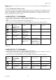
APR. 25, 2003 Channel 3 (4/ 5 / 6) Timer Control Output Programming Enter: 1. Turn the Ignition 'switch ‘ON/OFF’ 3 TIMES and stay in OFF position. 2. Push the Valet switch 8 times and hold it until four chirps with a long chirp is hearing then release the valet switch. You are now in the Alarm feature ‘IV’ programming mode. Timer Program: button 4 times, [4] LED flash, [4] siren/horn chirp to indicate 1-a. Press and release the transmitter your are in features “Channel 3 Timer Programming mode”.
APR. 25, 2003 2. Push the Valet switch 10 times and hold it until five chirps with a long chirp is hearing then release the valet switch. You are now in the Alarm feature ‘V’ programming mode. You can program or delete the password pin code as below: Program: button twice, [2] LED flash, [2] siren/horn chirp to indicate your are 1. Press and release the transmitter in features “Password Pin Code Programming mode”. 2.
APR. 25, 2003 RETURN TO FACTORY DEFAULT SETTING 1. Turn the ignition ON then OFF 3 TIMES and stay in OFF position. 2. Push the Valet switch 12 times and hold it until six chirp with a long chirp is hearing then release the valet switch. You are now in the “Return To Factory Default Setting” programming mode. 3.