
User Manual
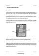
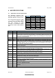
Table Of Contents
- ABBREVIATIONS
- INTRODUCTION
- PRODUCT DESCRIPTION
- HW SPECIFICATIONS
- SW SPECIFICATION
- REFERENCES
DSH, Datasheet 903501205 May 1, 2003
Zensys A/S ZM1220 Z-Wave Module Page 6 of 15
CONFIDENTIAL
The Application Connector interfacing the Z-Wave Module with the Application Module is a standard
2.00mm pitch 2x10 pin-row. The Application Connector contains the following signals:
• 11 General Purpose I/O pins (dual function)
• One interrupt input pin
• Serial UART interface
• SPI interface (Serial Peripheral Interface)
• Two ADC inputs
• Zero Crossing Detection input (used for dimmer applications)
• TRIAC control output (used for dimmer applications)
• Reset input
• 5V and 3V power inputs
• Ground
All 11 GPIO’s have a dual function meaning they support “special” signals (interrupt, SPI etc.) see Table
2. All signals on the Application Connector are 3.3V CMOS signaling compatible, and are all controlled
by the application SW.
The software modules handling the Z-Wave protocol and RF transmission are a part of the ZM1220
Z-Wave Module. OEM application software can be added to the Z-Wave protocol software via a well-
defined Application Programming Interface (API)[6].
In the following chapter the HW specifications for the Z-Wave Module is described. The specifications of
the ZW0102 Single Chip will not be described within this datasheet but can be found in [1].