
User Manual
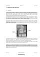
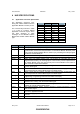
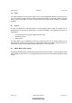
Table Of Contents
- ABBREVIATIONS
- INTRODUCTION
- PRODUCT DESCRIPTION
- HW SPECIFICATIONS
- SW SPECIFICATION
- REFERENCES

DSH, Datasheet 903501205 May 1, 2003
Zensys A/S ZM1220 Z-Wave Module Page 7 of 15
CONFIDENTIAL
4 HW SPECIFICATIONS
4.1 Application Connector Specification
The Application Connector inter-
facing the Z-Wave Module with the
Application Module is a 2x10 pin row.
Pin No. Pin Name Pin Name Pin No.
1 N.C. PROG_N 2
3 ZEROX PWM2 4
5 TRIAC INT0_n 6
7 AD1 IO9 8
9 N.C. MISO 10
11 5V CLK 12
13 GND MOSI 14
15 RESET_n TXD 16
17 VCC RXD 18
19 IO10 AD2 20
The connector layout shown in Table
1 is a part of a Zensys defined
Application Connector layout, which
has been designed to allow
exchange of the ZM1220 Z-Wave
Module with another Z-Wave Module
type.
Table 1 Application Connector Layout
Name I/O Description
IO[10:9] I/O IN/OUT[10:9]: General purpose I/O signals
INT0_n I Interrupt: Active low external interrupt signals. The signal is level or edge trigged. The
signals are also connected to the push button on the Z-Wave Module. When in power
down mode the Z-Wave Module MCU is woken up by activating this interrupt signal.
Can also be used as GPIO pin.
TXD I/O UART Transmit Data. Supports 2.4kbps – 56kbps. Can be used as GPIO pin.
RXD I/O UART Receive Data. Supports 2.4kbps – 56kbps. Can be used as GPIO pin.
RESET_n I/O Reset. Active low Z-Wave Module reset. The Z-Wave RF Controller chip has an
integrated reset circuitry. As mounting option a reset circuitry can be implemented on
the Z-Wave Module. Note: the reset circuitry will not be available on the future Z-
Wave Controller Chip Z-Wave Modules.
CLK I/O SPI Clock: Clock input for Flash programming. Can be used as master SPI clock
signal or GPIO signal.
MOSI I/O Master Out Slave In SPI interface: SPI data input used for Flash programming. Can
in normal operation be used as MOSI signal or as GPIO signal.
MISO I/O Master In Slave Out SPI interface: SPI data output used for Flash programming. Can
in normal operation be used as MISO signal or as GPIO signal.
PROG_N I Program Enable. Active low flash programming signal. The pin cannot be used after
programming. Programming instruction see section 4.8 and [6].
AD[2:1] I Analog-to-Digital converter input 1 and 2.
ZEROX I/O Zero Cross Detection: Zero cross detection signal used on dimmer modules detecting
120/240V zero crossing. Can be used as GPIO signal.
TRIAC I/O TRIAC Control. Can control a triac on the Application Module like light dimmer
modules etc. Can be used as GPIO signal.
PWM2 I/O Pulse Width Modulator Output. Used for frequency variation applications. Can be
used as GPIO signal.
VCC
Power Module 3.3V supply input. If the DC/DC is mounted 3.3V must not be added to this
pin from the Application Module.
5V Power Module 5V supply input. Should only be added if the 5V-to-3.3V DC/DC converter is
mounted.
GND Power Ground
Table 2 Application Connector Signal Description