
User Manual
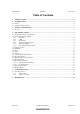
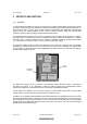
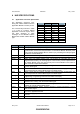
Table Of Contents
- ABBREVIATIONS
- INTRODUCTION
- PRODUCT DESCRIPTION
- HW SPECIFICATIONS
- SW SPECIFICATION
- REFERENCES
DSH, Datasheet 903501205 May 1, 2003
Zensys A/S ZM1220 Z-Wave Module Page 8 of 15
CONFIDENTIAL
4.2 Application Connector Signals
4.2.1 GPIO Pins
Some of the signals, which have a special feature, can also be used as General Purpose Inputs/Outputs
pin (GPIO) if wanted. All GPIO’s signals have true Read-Modify-Write functionality when used as general
digital I/O ports. The “special” purpose signals, which can be used as GPIO are listed in the table below.
• INT0_n
• TXD
• RXD
• MOSI
• MISO
• CLK
• TRIAC
• XEROX
For electrical characteristics see section 4.12.
4.2.2 UART
The ZM1220 Z-Wave Module features a full duplex Universal Asynchronous Receiver and Transmitter
(UART), which enables real time control of the Z-Wave Module, either by a CPU on the Application
Module or by a PC, requiring a RS232 driver on the Application Module. The interface supports the
following features:
• Data rate: 2.4kbps – 115.2kbps (default 9.6kbps)
• 8 bits per word
• One Stop bit
• No parity
• 3.3V signaling
When powering up the Z-Wave Module for the first time the data rate of the serial interface is 9.6kbps,
and can afterward be changed to the wanted data rate.
4.2.3 SPI Interface
The Serial Peripheral Interface (SPI) allows high-speed synchronous data transfer between the Z-Wave
Module and the Application Module. The Z-Wave Module SPI include the following features:
• Full-duplex, 3-wire Synchronous Data Transfer
• Master Operation
• LSB First or MSB First Data Transfer
• Four Programmable Bit Rates in Master Mode (f
sys
/8, f
sys
/16, f
sys
/32 or f
sys
/64)
The signals MISO, MOSI and CLK on the Application Connector are used. For SPI timing characteristics
see [1]. The SPI controller does not support Slave operation in normal mode only in flash programming
mode. If Slave operation is needed it must be implemented in SW using a GPIO pin.