
Owner manual

0571-02
1
ADVANCED CONTROL TECHNOLOGIES, INC.
Indianapolis, Indiana 46278
RB104 Installation Instructions
P/D 012408
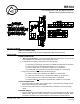
A10 120/208 VAC, 30A, Box Mount Receiver,
Standard and Extended Addressing
RB104
BEFORE YOU BEGIN...
READ ALL INSTRUCTIONS
Make sure your installation will conform to all applicable codes and requirements.
INSTALLATION
POWER CONNECTIONS:
1. Warning, shock hazard: To service the load, disconnect main power. Do not use the
manual ON/OFF override switch to disconnect load for service.
2. If single phase connection (120V) perform the following steps:
a) Connect the power supply neutral wire to the White wire marked “N” on the board.
b) Connect the line wire to the Black wire marked “L1” on the board.
c) Connect White wire “N” to Pink wire marked “PCC” on the board .
d) There should be no connection to the Red wire marked “L2” on the board.
3. If leg to leg connection (208V) perform the following steps:
a) Connect one line wire to the Black wire marked “L1” on the board.
b) Connect the second line wire to the Red wire marked “L2” on the board.
c) Connect Red wire “L2” to Pink wire marked “PCC” on the board.
d) There should be no connection to the White wire marked “N” on the board.
OUTPUT CONNECTIONS:
1. Connect the load to the GREY wire (normally open), or the BLUE wire (normally closed)
lead, and the VIOLET wire (common) lead.
2. See the "Relay Output" section in the specifications for maximum current and voltage
ratings.
EXTERNAL SWITCH:
1. Connect a switch to the removable terminal block P3. The switch may be any dry-contact
switch or relay. When the contact is closed the output relay will remain energized. When
the switch is opened the relay will default back to the last PCC command received.