
Manual

0692-01
1
RF124 Installation Instructions
P/D 013106
ADVANCED CONTROL TECHNOLOGIES, INC.
Indianapolis, Indiana 46278
BEFORE YOU BEGIN...
READ ALL INSTRUCTIONS
Make sure your installation will conform to all applicable codes and requirements.
TEST FOR SIGNAL STRENGTH AND NOISE...
using appropriate test equipment. It is necessary to test the installation in the actual operating
environment. The amount and types of line loads may reduce the strength of the transmitted signal
and/or electrical noise may cause interference with the transmitted signal. Proper installation may
require additional couplers, filters or repeaters. Special coupling devices are required to allow signal
to be distributed to all phases and zero-crossings in multi-phase and multi-transformer distributions.
IF YOU HAVE ANY QUESTIONS...
Consult your nearest Engineered System Center (ESC) for additional information.
There are no field repairable assemblies on this unit. If service is needed, the unit must be returned
to the ESC where purchased. Contact your ESC for return details.
INSTALLATION
CAUTION! Make all connections with the POWER OFF to avoid injury to the installer or damage
to the device. WARNING: SHOCK HAZARD. Do not use the manual ON/OFF switch on the RF
to disconnect the load for service. Signal can cause it to turn ON.
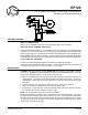
1. Strip 3/4" of insulation from the ends of the conductors and make connections as shown in the
Wiring Diagram. Connect line and neutral to the BLACK and WHITE flying leads. Connect the
load between a power source and the two BLUE wires. When the relay is turned ON the LED
illuminates.
2. Check connections to be sure they are tight and no bare conductors are exposed.
3. Make sure the load or installation does not exceed the device rating.
4. Install into a 4" x 4" electrical box. Clean the mounting surface, remove the protective film from
the adhesive tape and firmly press the module in place.
NOTE! Do not install within four inches of fluorescent ballast.
The RF124 features two operating modes: Normal Mode and Configuration Mode. The Normal
Mode is the state in which the device performs its primary function. The Configuration Mode allows
the user to specify the address by which the device may be controlled, and allows the user to enable
“All Lights On, All Units Off, All Lights Off commands” (disabled when address is set) or disable
“polite mode” and enable “rude mode”.
RF124
A10 120 VAC, 20A, Isolated Contact Relay Fixture Receiver,
Standard and Extended Addressing