The Alien Pro Digital Video Recorder Operations Manual ALIEN504 Models ALIEN508 ALIEN516 Networkable and Mobile Phone monitoring Version 8.
Index Safety Precautions .............................................................................................. 5 Chapter 1 Product Introduction.........................................................… ... 1.1 Summary ...................................................................................................... 1.2 Model Description ...................................................................................... 1.3 Features ...........................................................
Chapter 6 Advanced Operation Guide ................................................. 36 6.1 User Management ...................................................................................... 6.1.1 Add Users .............................................................................. 6.1.2 Delete User ............................................................................. 6.1.3 Password Modification .......................................................... 6.1.4 User Rights ...................
Appendix A HDD Capacity Calculation .............................................. 64 Appendix B DVR Connector Definition ........................................... 65 Appendix C Specifications ........................................................................... 69 Appendix D Quick Search Manual Guide ..................................... 70 Appendix E Days Recording per HDD for ALIEN504............... 71 Appendix F Days Recording per HDD for ALIEN508 ..............
Safety Precautions Caution: To reduce the risk of electric shock, please do not remove the cover without powering down. There are no user-serviceable parts inside. Important Safeguards: 1. 2. 3. 4. 5. 6. 7. 8. 9. 10. 11. Please read these instructions before use. Do not use this apparatus near water. Clean only with a dry cloth. Do not block any ventilation openings. Install in accordance with the manufacturer's instructions.
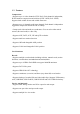
Chapter 1 Product Introduction 1.1 Summary The Alien Pro series Network Digital video Recorders are excellent digital surveillance products. They adopt an embedded MCU (Microprocessor Control Unit) and an embedded Real-Time Operating System (RTOS). They combine the most advanced technology in the Information Industry such as video and audio encoding/decoding, hard disk recording and TCP/IP transmission.
1.3 Features Compression: •Supports up to 16 video channels (NTSC/PAL). Each channel is independent, H.264 hardware compression and real-time (NTSC 30FPS, PAL 25FPS). Supports both variable bit rate and variable frame rate. •Supports up to 16 channels audio input channels. Each channel is independent OggVorbis compression and the bit rate is 16Kbps. •Compressed video and audio are synchronous. You can select either mixed stream (video and audio) or video only.
•Supports Privacy Mask (blanks portions of camera view). •Supports camera block alarm. •Supports mult-synchronous playback. Support play forward, backward, pause, frame by frame, etc. •Supports play back by files or by time/date. •Displays local record status. PTZ: •Supports multiple PTZ protocols. •Supports preset, sequence and pattern. Alarms: •Supports exception alarm, motion detection alarm, external alarm, etc. Miscellaneous: •Supports IR Remote control. •Supports RS-485 keyboard.
•RS232 supports transparent channel function so that the remote PC can use DVR to control serial devices. Note that RS232 is not supported. •Supports bi-directional audio or one-way audio broadcast. •Supports IE to view and configure the DVR. •Supports activity log. 1.4 Typical Application Note that the above functionality depends on the model purchased.
Chapter 2 Installation 2.1 Check DVR and its Accessories Please check the contents of the shipping container. If any of the items are missing please contact your supplier. 2.2 HDD Installation If you have not purchased Hard Drives for this DVR you can calculate the total capacity you need (refer to Appendix A). Installing the hard disks should be performed by a qualified person.
5. Place the hard disks you wish to install on a table with the mounting side facing upwards. 6. Place the metal hard disk bracket on top of the hard disks, and fasten each hard disk with 4 screws to the bracket. 7. Reinstall the bracket and then connect the power and data cables to the HDD and main board.
8. Check all connections, and reinstall the metal cover on the DVR. 9. Connect the power cable and power on the DVR. 10. Press [MENU] key to enter into DVR main menu. Go to the "Utilities" menu and choose "Hard disk" to format the hard disks. Check that all installed disks are detected by the DVR (shown in the menu). Choose "Format" and select "All" to format all hard disks. When all drives are formatted a confirmation message will be shown on the screen.
2.3 ALIEN504 Rear Panel of 4 way unit Number Interface 1 Video Input Audio Input 2 Description Standard BNC Standard BNC Main Video Output Main Audio Output Connect CCTV monitor, output video and menu Local Audio Output 3 Line In USB Interface Audio line input for voice talk USB Memory stick, USD HDD, USB CD/DVD or USB mouse 4 VGA Interface VGA Display 5 RS232 Network Interface Connect RS232 devices. See Appendix B. Connect Network devices. See Appendix B.
2.
2.5 External Alarm In/Out Connection Alarm input dry contact: Alarm input port (dry contact): G (GND): Connect the GND of sensor. 1~8: Alarm input, support normally open/normally closed. 0: Reserved. Alarm output: 1G ~ 4G: 4 relay output. Alarm output connection: Powering Up: Note: Complete all cable connections before powering on the DVR. 1. Switch on all connected equipment. 2. Connect the power cable to the unit. 3. Switch on the power supply power switch.
Chapter 3 Operational Instructions 3.1 DVR Front Panel 2 1 4 7 5 3 6 Number 1 Type Name 1 ~ 16 2 Camera Indicator Lamps 3 Power Power 4 Status Lamps 5 Input Keys Description Infra Red receiver Ready Status Alarm Modem HDD Link Tx/Rx Numeric Keys F1 F2 Menu ESC Play 6 Function Keys REC Edit PTZ A 16 Shows 1 ~ 16 camera status. Green means recording; Red means network transmission; Orange means recording and network transmission. Device switch with power indicator light.
1. Multi Screen selection 2. Switch menu mode into live view 3. [FOCUS-] in PTZ mode [ZOOM+] in PTZ mode 1. Switch main/spot video output control mode 2. [ZOOM-] in PTZ control PREV 6 7 Function Keys Control Keys INFO Main/Aux Direction Keys Composed of up, down, left and right arrow. 1. Menu mode. Use direction keys to select, press [Enter] or [Edit] key to edit. 2. PTZ direction control. 3. Playback speed control. 1. Menu confirmation 2. Select ü or x to enable or disable 3.
Loading the batteries into the IR controller: 1. Remove the battery cover. 2. Insert the battery. Ensure that the poles (+ and -) are correctly positioned. 3. Replace the battery cover. Enable the IR Remote Controller: 1. Press the [DEV] key, input the DVR device ID (default is “88”. It can be changed in the “Display”menu) and then press the [ENTER] key. 2. The “STATUS”lamp on the DVR front panel will turn green, indicating that you can use IR controller to operate the DVR. Disable the IR controller: 1.
3.3 OSD Menu Description 3.3.
3.3.2 Navigating Menus The Operation Manual provides step by step instructions in the early chapters. The later chapters provide directions without indicating some of the individual key presses because you will have learned the basics by then. This section provides a brief overview of navigating through the menus using the control keys and by using the mouse. With this information you will be able to quickly access most DVR functions. See the detailed text for further information on particular features.
•Switch VOUT: Switch to the “Spot”monitor output. (Depends on model purchased) Caution: If you select “Switch VOUT”you will lose mouse control of the main monitor. The mouse pointer will move to the Spot display. If you have a monitor connected to the “Spot”output you can right click and select “Switch VOUT”to return to the main display control. If no “Spot”monitor is available you will not be able to return to the main output using the mouse.
the previous menu and back to live mode. Walk through the following list of items to familiarise yourself with key operation. Starting from the live display: •Press the “Menu”key to enter the “Main Menu.” •Use the Up/Down arrow keys to enter sub menus. •Select the Display Menu to view the available options. •Use the arrow keys to move to selected menu options and press “Enter”to select. Enter (or, Edit) will also change check box selections. •Select the “Setup”button next to time/date.
3.3.3 Menu Operation How to access the menus: •Press the [MENU] key to enter the DVR main menu •Press the [PLAY] key to enter the playback menu •Press the [REC] key to enter the manual record menu •Press the [PTZ] key to enter the PTZ control interface Note: You must input a valid user name and password. The default user name is “admin”and password is “12345”. Main Menu Description: Main menu: One section of the menu screen will be highlighted to indicate the input cursor position.
1. Check Box: Provide 2 options. “ ”means enable and “× ”means disable. Select either [ENTER] or [EDIT] to change selections. 2. List Box: Provides more than 2 options. However, only one of them can be selected. You can press [ENTER] or [EDIT] to enter into edit mode, then use [ ] and [ ] to select one option. For example, on the right side of “Select Camera”, there is a list box for you to select one camera. 3. Edit Box: Allows you to input characters. Press the [EDIT] key to enter the edit mode.
Chapter4 Basic Operation Guide 4.1 Power on Note: It is always a good idea to check the power supply before connecting the AC cable and applying power. The DVR is equipped with a universal power supply that will accommodate 120/240VAC, 50/60Hz. Units with an input power selector switch must be placed in the correct input voltage position for the local area before applying power. Switch the main power switch off before inserting the AC power cord.
Icon Colour White Yellow Pink Green Blue Red Action Video signal lost View tampering alarm Motion and External alarm No alarm Motion alarm External alarm Press the numeric keys to switch to an individual camera in live view. If the DVR has less than 10 channels, press one numeric key to switch to the corresponding channel. For example: Press [2] to view camera #2. If the DVR has 10 or more 10 channels, press two numeric keys to switch to the corresponding channel.
3. Press [ENTER] to confirm the entry. Note: An incorrect user name/password entry will result in an audible alarm. After three incorrect entries the DVR will switch to the live display mode. 4.4 PTZ Control Note: Ensure that PTZ communication parameters have been configured properly before attempting normal operation. Your password must have PTZ control enabled in order to control cameras. Note: Please refer to “PTZ Setup”in section 6.14.
4.5 Manual Record Note: In order to perform this function the DVR must have drives installed and formatted and the user login password must have “Record”enabled. Manual record is lost after a reboot. Manual record: 1. In the live view mode, press the [REC] key. In the display login dialog, select a username and input the correct password to enter into the “Manual Record” interface. 2. In menu mode, press [REC] to enter the “Manual Record”interface directly.
4.6 Playback Note: The user must have “Playback”permission associated with the user name and password in order to enter playback mode. Playback interface: In the live view mode, press the [PLAY] key. In the display login box, select a username and input the correct password to enter the “Playback”interface. In the menu mode, press the [PLAY] key to enter the “Playback”interface directly. Playback Menu: The Playback interface has the following selections: Chan: Rec.
10. Copy: Start backup. 11. Backup Today: Backup all recorded files created today. 12. Coding Format: You can select either an H264 backup or AVI backup. 13. Backup: Use this backup option for option 12 backup. There are two playback modes: 1. Search and playback a file: In the playback menu select a channel to search, and a record type. Move the “Active Window”to the “Search”button and press [ENTER]. The DVR will search and list the matched files. 2.
6. Copy segment: [EDIT] to start copy, [EDIT] again to end copy. 7. Exit: [ESC] 8. Playback switch: When in 2-ch playback, press [PREV] to switch between main channel and second channel. Note: When the DVR is performing multiple tasks the actual play speed may not match the speed selected. Exit playback: 1. From the playback interface, press [ESC] to return to the Live mode. 2. From the playback interface, press [MENU] to enter into main menu. 3. Press [REC] to enter the manual record menu. 4.
Note: If backup device is not connected correctly, or the DVR does not detect the backup device, a “Device Error” message will displayed. Backup video clips: You can back-up video clips as the file is being played back. The steps are: 1. Search for and select the video you want to export. 2. Play the video and press [EDIT] to start saving the clip. 3. Press [EDIT] again to mark the end of the clip. This clip is ready for export. 4. Repeat the steps above to select additional clips (up to 30 total). 5.
Shutting down the DVR using the menu: 1. Enter the “Utilities”menu. (Main, Utilities). 2. Move the “Active Window”to “Power Off”and press ENTER. 3. In the power off menu, press “Confirm”to shut down the DVR. 4. Enter a user name and password as required. Power off using the [POWER] key on the front panel or IR Remote: 1. In the “Live”mode press and hold the [POWER] key (on the front panel or IR Remote) for more five seconds. 2. A power off display will ask you to confirm your selection. 3.
Chapter 5 Main and Spot Monitor Output 5.1 Main and Spot Monitor Output The DVR has one main video output and one spot output. The main video output provides access to the DVR menu. The spot output does not. It is intended for normal operation, not system setup. The spot output is an additional composite monitor used for viewing live video, playback video and for local PTZ control. Accessing the Main and Spot monitor outputs: 1.
12 and 16 displays are available in 16 channel units) See “Layout”below for setup details. 3. Switch Time: This control sets the sequence dwell time in the sequence mode. Each sequencing view will remain on the screen for the amount of time selected. Options include 5, 10, 20, 30 seconds, 1, 2, 5 minutes and never (sequence off).
Chapter 6 Advanced Operation Guide Only users that have “Parameters Setup”permissions assigned to their user name can perform the operations in this section. When the following parameters are modified and saved, you must reboot the DVR before the new parameters take effective. Parameters mentioned earlier do not require a reboot.
6.1.1 Add Users Additional users may be added by those with admin rights: 1. Enter the “User Management”menu (select User from the main menu). 2. In the “User Management”menu, select the “Add” button and press [ENTER]. 3. Input the new user name in the pop-up dialog and press [ENTER] (up to 15 users can be added). Setup the password for a new user: 1. After you add a new user, the password is null (no password). You can skip this step if you do not want to change the password. 2. Enter the desired password.
Note: If there is an error in entering or verifying the password an error message box will appear. Denoting that the “Password Change Has Failed”. In this case, press [ENTER] to return to the password edit box, and re-enter the new password and verify again. 6.1.4 User Rights Setup permissions for new users: 1. In the users list box of the “User Management”menu, use the [ á ] [ â ] keys to select the user name, then use the [ à ] key to move to the “Set Privileges”button and press [ENTER].
4. Log: Remote view of the DVR log 5. Utilities: Remote upgrade firmware, format HDD, reboot DVR and shut down DVR etc. 6. Audio: Client talks with DVR 7. Live view: Network live view 8. Alarm: Remote control of DVR alarm output 9. Local Video Out: Remote imitation of front panel operation 10. Com Control: DVR RS-232 transparent channel function. MAC address: This MAC address is not the address of DVR. It is the MAC address of the PC that will access the DVR.
6.3 Video Standard and VGA Setup Video standard: Changing the video format (NTSC/PAL) is easily performed in the Display menu. 1. Select the “Display Menu from the Main Menu. 2. Select the “Video Standard”button and select the appropriate standard for your area (NTSC/PAL). VGA setup: You can define the VGA resolution and refresh frequency in the “Display”menu. Options include: 1024*768/60Hz, 800*600/60Hz and 800*600/75Hz. 1. Select the Display Menu. 2. Use the [ á ] [ â ] keys to select the desired format.
5. Select “Confirm”to return to the previous menu. Selecting the Date/Time Display Settings: You can modify the Time/Date display properties for each camera, including display status, position and format. You can copy the properties of one camera to all cameras. These modifications are made in the “Image”Menu. Selecting Camera Date/Time display settings: 1. Enter the “Image”Menu and select a camera to modify. 2. Select the “Date OSD.
6.5 Image Setup 6.5.1 Camera Name Setup Camera Name: You can modify camera names in the “Camera Input Adjustment” Menu. Note: Camera names can’t be copied to other cameras. 1. From the “Main Menu,”select the “Image”menu. 2. Select a camera to configure. 3. Select the “Name”entry to modify the camera name. Move the “Active Window”to the camera name edit box and press [EDIT] to enter the edit mode. You can input numbers, uppercase and lowercase characters (refer to Chapter 3.4).
2. Select the “Adjust”button for each parameter; Brightness, Contrast, Saturation and Hue. Press the [ENTER] key to access the parameter overlaid on an image of the selected camera. Use the [ â ] [ á ] keys to adjust as you watch the image change. When you are satisfied with the results, press [ENTER] to return “Image Setup”menu. 3. Repeat the steps above to adjust any other cameras. 4. Press “Confirm”to save the settings, or “Cancel”or [ESC] to abort. 6.
press the [EDIT] key. The yellow pane will turn red. Use the [ â ] [ á ] [ à ] [ ß ] keys to extend the red privacy mask area. •Note: Press the [A] key to clear all mask areas. •The maximum mask area size is 8*8 panes. Up to four mask areas are allowed on each camera. •Once you have the area(s) defined, press [EDIT] to accept, or [ESC] to cancel. Saving the masked area: •In “Camera Input Adjustment”menu, press the “Confirm”button to save the mask area, or press “Cancel”to abort.
Note: Only one view tampering area can be setup per camera. 7. Alarm schedule setup: When there is a view tampering alarm present, the DVR will handle the alarm based on the schedule selected. You can set 4 periods for each day of the week. You can copy the schedule of one day to other days. Note: Time periods must not overlap. You must reboot the DVR before the settings take effect. 8.
5. Setup alarm policy: You can select one or more response: “On Screen Warning”, “Audible tone”, “Upload to Center”and “Trigger Alarm Output”. Use the [ â ] [ á ] and [EDIT] key to enable or disable items. “×”is disable and “ü ”is enable. 6. Save alarm setup: After making selections, press “Confirm”to return to the “Camera Input adjustment”menu. In this menu, press “Confirm”to save current Camera parameters and return to main menu. 7.
4. Motion area setup: You must define motion areas so that DVR will respond when there is motion in those areas. Move the “Active Window”to the “Area” button on the right side of sensitivity selection box and press [ENTER] to enter the “Motion Area Setup”interface. The screen is divided into 22*15 panes (22*15 PAL). There is one yellow panel on the upper left side. The motion area setup steps are the same as that of mask area setup (refer to chapter 6.6).
2. Motion alarm record channel setup: Once a motion alarm has been detected that information can be used to trigger other alarm conditions. In the “Motion Alarm Handle”menu you can select one or more channels to record based on a camera motion alarm input. Use the [ENTER] or [EDIT] key to enable the flag (“ü ”). Note: To enable the linked recording function the affected channels must be enabled in the “Recording”menu.
6.10 Live View Setup The “Preview”menu provides access to live view parameters. In “Preview”(live) menu, you can setup live mode, screen sequence time, enable or disable audio and live view screen formats. 6.11 Recording Setup Select “Recording”from the main menu. Recording Menu Functions: •If HD Full: There are two options: “Overwrite”and “Stop recording”. If you select the “Overwrite”option, when all HDDs in DVR are full, the DVR will overwrite the earliest recorded files and continue recording.
•Bit Rate: You can select different bit rates to accommodate different settings of resolution and frame-rate options include: (bps): 32K, 48K, 64K, 80K, 96K, 128K, 160K, 192K, 224K, 256K, 320K, 384K, 448K, 512K, 640K, 768K, 896K, 1M, 1.25M, 1.5M, 1.75M, 2M and “User define”. The appropriate max bit rate selection is related to the resolution selected. If you select a high resolution, you must select high bit rate. For CIF resolution, the typical max bit rate is 384K~768Kbps for real time compression.
All day Recording Setup: 1. Enable “Enable Rec”and enter the recording “Schedule”menu. 2. In the recording menu, use [ENTER] or [EDIT] to enable the record function (“ü ” flag). Select the “Schedule”button to enter the recording schedule menu. 3. Select a day and enable all day recording: Day selection options: Monday, Tuesday, Wednesday, Thursday, Friday, Saturday and Sunday. Use the [ ] [ ] key to select a day.
options: Monday, Tuesday, Wednesday, Thursday, Friday, Saturday and Sunday. Navigate to the “All Day”check box and ensure that it is deselected ([ENTER] or [EDIT] until an “×”appears in the box). 4. Setup time period and record type: You may select up to four time periods for each day and each time period can select a different record type. Input the start time and the stop time for each time period and select the record type for each time period.
5. Alarm trigger record channel setup: You can select channels to record for each alarm input. In the sub menu, you can use [ENTER] or [EDIT] to enable the record channel. “×”means disable and “ü ”means enable. Note: In order to trigger the channel to record, the channel must be enabled in the “Recording”menu. 6. Schedule for alarm handle method: When a schedule is enabled, external alarms will trigger a DVR response only during the scheduled times. 7.
Note: Please make sure that the PTZ you are using can support preset, sequence and cruise (pattern) functions. Also make sure that you configure them in the PTZ menu. One external alarm input can trigger multiple PTZ links. 4. Copy the parameters: You can copy the parameters of current alarm input to other external input. 5. Save setup: In “Alarms”menu, press “Confirm”button to save the parameters. Press “Cancel”button or [ESC] to abort. Alarm relay output setup: 1.
6.13 Network Setup This section describes network parameters for communication with remote software. Note: If any network parameter is modified, you must save and reboot the DVR before changes will take effect. In main menu select the Network option to access network setup. 6.13.1 Network Settings •IP address: The IP address must not be in conflict with other IP addresses on the network. If there is a DHCP server in the network, you can set the IP as “0.0.0.0”, save and reboot the DVR.
Multicast IP: D-class IP addresses, from 224.0.0.0 --- 239.255.255.255. If you do not use the multicast function, you do not need to set this parameter. Some routers will prohibit multicast functions for security reasons. Remote Host IP and Port: If you enable this IP and port the “Upload to Center” option on exception alarm will notify the Upload Center. You can use the SDK to develop this center software function.
6.14 PTZ Setup There is one RS-485 port on the DVR rear panel used for PTZ control. 6.14.1 PTZ RS485 Connection Connect DVR/DVS RS-485 port Pin “T+”with PTZ Pin “A”. Connect DVR RS-485 port Pin “T-“with PTZ Pin “B”. If DVR RS-485 port is an RJ45 interface, please refer to DVR user manual for the RS-485 pin definition. 6.14.2 PTZ Settings Configure the RS-485 parameters to match your PTZ protocol. In the main menu, select the PTZ setup option. PTZ menu Options: •Select channel: Select a PTZ camera.
6.14.3 PTZ Control In “Preview”(Live view) mode, press the [PTZ] key to enter the PTZ control mode. The screen is in camera 01 PTZ control mode. Press the [UP] [DOWN] [LEFT [RIGHT] keys to manually position the dome. 6.14.4 Preset Setup The Preset function allows the dome to return to a predetermined position (pan, tilt, zoom, iris and focus). In the PTZ menu select the setup option (next to “Preset).”The DVR can save up to128 preset positions.
2. In the “Sequence”setup menu, first input the sequence number (1 –16). Each sequence is made up of a series of preset positions. Each “sequence” includes the preset number, dwell time (how long it will stay in each position) and dwell speed (how long it takes to move to the next sequence position). Press the “Add”button to add a preset point. 3. Press “Confirm”button to save the cruise point into the sequence. 4.
Chapter 7 Utilities The “Utilities”Menu includes several special options: Enter the “Utilities”menu from the main menu: Utilities Options: •RS232: Option not supported •Default Parameters: Reset to factory defaults. •Firmware: Upgrade firmware (USB ,CD or FTP). As this may cause permanent damage if incorrectly installed this option requires supplier’s confirmation. •Hard Disk : Format drives. •Alarm Outputs: Silence the alarm tone. •Reboot: Reboot the DVR. •Power Off: Turn off DVR power.
7.3 Alarm Outputs •Clear an alarm in progress. This is the only way to stop an alarm when there is no alarm time designated. Select “Stop.” 7.4 Reboot •Reboot the DVR. 7.5 Power Off •Shut down DVR. 7.6 View Log To view the log recorded in the DVR HDD. In “Utilities”menu, press “View Log”to enter the “Log”menu: If you want to view the log based on default option, just press the [ENTER] key. A list of matching file segments will display in the view log window. The DVR will list all matched information.
Viewing the Alarm Log: 1. Select a Query type, a Major For “Query”item, select “By Type”to active “Major Type”and “Minor Type”items. 2. For “Major Type”option, select “Alarm”option. For “Minor Type”option, select one of following options: All, External Alarm In, External Alarm Out, Motion Detect Start, Motion Detect Stop, View Tamper Start, and View Tamper Stop. 3. Move “Active Window”to the “Search Log”button and press [ENTER] to start searching. 4.
Chapter 8 Firmware Upgrade It should be noted that ‘Firmware Upgrade’is a non ‘User’configurable function. Uploading incorrect or incompatibly firmware may result in permanent damage to your equipment and will invalidate any warranty.
Appendix A HDD Capacity Calculation 64
Appendix B DVR Connector Definition RS485 Connector Materials and tools required to make the cable: •CAT5 cable (8 pins). •Standard RJ45 connector. •Crimping tool for RJ45 connectors. Pin Definition: Pin definition for Standard RS-485 serial port RJ45 plug-in Note: The configuration at the other end of the cable depends on the product it is being connected to. UTP Network Connection Materials and Tools Required: •CAT5 cable: The length depends on the installation, no to exceed Network guidelines (100m).
End to end relationship of a direct cable Cross-over cable: Use the following method to make a network cable when the DVR is connected directly to the client-end PC. End to end relationship of a cross-over cable RS232 Connection Materials and Tools Required: •CAT5 cable (4 twisted pairs). •Standard RJ45 plug connector. One or more DB9 plug-in.
•An RJ45 crimp tool. •Soldering iron and solder. Pin Definition: Configure the RJ45 according to the following pin definition (I means DVR input, O means DVR output). The configuration of the cable changes depending on the DVR model. The following four configurations are provided. 1. The serial port of the DVR is connected with a DTE device with DB25 plug-in (terminal like computer, door access etc). Connection for RJ45 and DB25 (DTE) DTR 2.
Connection for RJ45 and DB9: 3. 25-pin to 9-pin converter internal connection is defined as follows: Connection for DB25 and DB9: 4. The serial port of the DVR is connected with a DCE device (like a MODEM); one end of the cable is an 8-pin RJ45 plug. The other end is DB25 pin connector.
Appendix C Specifications Model Video Compression Preview Resolution Recording Resolution Video Input Main Video Output Aux Video Output Frame Rate Stream Type Max Bit Rate Audio Input Main audio output Aux Audio Output Audio Compression Audio Comms Interface RS485 Port Keyboard Interface SATA Interface USB Interface VGA Interface External Alarm In Relay Output Power Supply Power Consumption Working Temperature Working Humidity Size Weight ALIEN504 ALIEN508 ALIEN516 H.
Appendix D Quick Search Manual Guide Function Type Description User Management Create and delete users. System has one default Administrator who can create 15 users and define their rights. Modify password Security function Password Management HDD Management Recording Mode HDD Recording Recording resources Playback Backup Preview Mode PTZ control Local Monitoring Network Motion Detect Alarm input Relay output Mask View Tampering ASDL View log Chapter 6.1 6.1 Format HDD and HDD information 7.
Appendix E Days Recording per HDD for ALIEN504 4CIF 2CIF CIF DCIF 2CIF CIF CIF QCIF QCIF Frames Per Second Resolution The following are based on continuous days recording for 4 channels @ 512 Kbps 6 12 25 6 6 12 6 25 12 80Gb 160Gb 250GB 320Gb 400Gb 500Gb 750Gb 1000Gb 3.2 3.2 3.2 5.2 6.5 6.5 13.2 13.2 26.4 6.5 6.5 6.5 10.5 13.2 13.2 26.4 26.4 52.8 10.3 10.3 10.3 16.4 20.5 20.5 41.2 41.2 82.4 13.2 13.2 13.2 21.0 26.3 26.3 52.7 52.7 105.5 16.4 16.4 16.4 26.3 32.9 32.9 65.9 65.9 131.9 20.5 20.5 20.
Appendix F Days Recording per HDD for ALIEN508 4CIF 2CIF CIF DCIF 2CIF CIF CIF QCIF QCIF Frames Per Second Resolution The following are based on continuous days recording for 8 channels @ 512 Kbps 6 12 25 6 6 12 6 25 12 80Gb 160Gb 250GB 320Gb 400Gb 500Gb 750Gb 1000Gb 1.5 1.5 1.5 2.5 3.3 3.3 6.5 6.5 13.2 3.2 3.2 3.2 5.2 6.5 6.5 13.2 13.2 26.3 5.1 5.1 5.1 8.2 10.3 10.3 20.5 20.5 41.2 6.5 6.5 6.5 10.5 13.2 13.2 26.3 26.3 52.7 8.2 8.2 8.2 13.2 16.4 16.4 32.9 32.9 65.9 10.2 10.2 10.2 16.4 20.5 20.
Appendix G Days Recording per HDD for ALIEN516 4CIF 2CIF CIF DCIF 2CIF CIF CIF QCIF QCIF Frames Per Second Resolution The following are based on continuous days recording for 16 channels @ 512 Kbps 6 12 25 6 6 12 6 25 12 80Gb 160Gb 250GB 320Gb 400Gb 500Gb 750Gb 1000Gb 0.8 0.8 0.8 1.3 1.6 1.6 3.2 3.2 6.5 1.6 1.6 1.6 2.6 3.2 3.2 6.5 6.5 13.1 2.5 2.5 2.5 4.0 5.0 5.0 10.3 10.3 20.5 3.7 3.7 3.7 5.2 6.5 6.5 13.1 13.1 26.3 4.0 4.0 4.0 6.6 8.2 8.2 16.4 16.4 32.9 5.1 5.1 5.1 8.2 10.3 10.3 20.5 20.5 41.