Pulsar 710 Controller Operator’s Manual & Installation Guide Pulsar 710 Manual
1595.050017 REV- Manual, Operation, Pulsar 710 Packing list, Pulsar 710 The shipping container should contain the following items: Pulsar 710 controller (1) Installation CD (1) Pulsar 710 operator’s manual (1) 3 Pin, Trigger input connectors (2) 2 Pin, Power input connector and cable (1) USB cable (1) Advanced illumination 24 Peavine Drive Rochester VT 05767 802.767.3830 2 a d v a n c e d i l l u m i n a t i o n .
Pulsar 710 Controller Operator’s Manual Table of Contents Section: 1.0 Introduction . . . . . . . . . . . . . . . . . . . . . . . . . . . . . . . . . . 6 1.1 Safety 1.2 Warranty 1.3 Return Policy Section: 2.0 Features . . . . . . . . . . . . . . . . . . . . . . . . . . . . . . . . . . . . . . . 7 2.1 Four Channels 2.2 User Interface 2.2.1 Remote Operation 2.2.2 Local Control 2.3 Diagnostics Section: 3.0 Quick Start . . . . . . . . . . . . . . . . . . . . . . . . . . . . . . . . . . . . 8 3.
4.1.13 Trigger Pass Through 4.1.14 Trigger Delay 4.2 Pulsar 710 Controller Cable Connections 4.2.1 Power 4.2.2 Trigger 4.2.3 RS 232/485 4.2.4 USB 4.2.5 Light Head 4.3 Pulsar 710 Status Indicator Lights 4.3.1 Green 4.3.2 Amber 4.3.3 Red 4.4 Host Computer Control (Remote) 4.4.1 Software Installation 4.4.2 Running Under Host Computer Control 4.4.2.1 Configure Pulsar 710 4.4.2.2 Launch Pulsar 710 Controller Utility 4.4.2.
List of Figures: Figure 1: Pulsar 710 front panel . . . . . . . . . . . . . . . . . . . . . . . . . . . . . . . . . . . . . . . . . . . . . . 9 Figure 2: Pulsar 710 rear panel . . . . . . . . . . . . . . . . . . . . . . . . . . . . . . . . . . . . . . . . . . . . . . . 9 Figure 3: Attaching a light to the Pulsar 710 . . . . . . . . . . . . . . . . . . . . . . . . . . . . . . . . . . 9 Figure 4: Status indicator lights . . . . . . . . . . . . . . . . . . . . . . . . . . . . . . . . . . . . . . . . . . . . .
Section: 1.0 Introduction The Pulsar 710 Controller, used in conjunction with an external 24VDC power supply, is a compact, 4 channel, high power current source incorporating a wide range of flexibility for selecting the operating parameters. The unit can be configured to operate as a strobe unit or a constant current (DC) source. The unit may be controlled and operated locally (with some restrictions) or remotely via a USB interface and host computer.
for any implied warranties, including implied warranties or “merchantability” and “fitness for a specific purpose.” Ai cannot be held responsible for the unauthorized or inappropriate use of our products. NO LIABILITY FOR CONSEQUENTIAL DAMAGES. In no event shall Advanced illumination, Inc. be liable for consequential, special, incidental or indirect damages of any kind arising from the sale or use of products. 1.3: Return Policy Standard Products may be returned within 30 days of receipt of the order.
set between 1 and 999 microseconds in 1 microsecond increments at pulse repetition rates up to 200 Hz. 2.2 User Interface 2.2.1 Remote Operation: Remote operation via a host computer allows the operator to make full use of the flexibility offered by the Pulsar 710. Communication is accomplished by a USB interface. Operating parameters are set by user friendly Windows based Pulsar 710 controller software. Supported operating systems are Windows 2000 and Windows XP. 2.2.
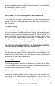
EXTERNAL TRIGGER INTERFACE CONNECTOR RS232/485 INTERFACE (FUTURE IMPLEMENTAION) EXTERNAL TRIGGER 100's 10's 1 2 3 8 7 1 4 0 5 9 2 3 8 7 1 4 0 6 5 9 1's 6 2 3 8 7 MODE USB RS232/485 4 0 4 5 6 1 2 3 VDC INPUT POWER STATUS POWER 0 5 9 ERROR 1 6 + - MAIN POWER SWITCH USB INTERFACE TO HOST COMPUTER VARIABLE CONTROL ROTARY SWITCHES LED STATUS INDICATOR MODE CONTROL DIP SWITCHES EXTERNAL DC POWER INPUT CONNECTOR Figure 1: Pulsar 710 front panel 3.1.
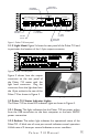
PULSAR 710 STATUS INDICATOR LIGHTS 3.2.3 Red: The red light blinks an error code in the case of an error condition. The condition is indicated by three sets of sequential flashes. For example: 4 flashes followed by 2 flashes followed by 3 flashes indicates an error code of 423 which signifies that the main power switch is off. Two common error codes are: POWER ERROR STATUS POWER 0 1 Figure 4: Status indicator Lights • 351: No light head detected. • 423: The main power switch is off.
Section: 4.0 Operation The following section details the procedures for operation of the Pulsar 710 Controller and defines its various operating modes. 4.1 Definition of Terms The following terms are used within this manual and, more generally, in relation to machine vision illumination. 4.1.1 Constant Mode: The Pulsar 710 produces a constant output.The current is determined by the control settings. The timing settings are not available in this mode. 4.1.
4.1.5.1 LED Forward Voltage: The forward voltage drop across an LED (Vf) depends upon the nature of the semiconductor junction and the current through the LED. The specified Vf for an LED is usually given at its recommended operating current. Please note that when driven by high current pulses, Vf can increase by 10 to 20 times. For this reason voltage levels at the Pulsar 710 output can be as high as 100 volts. 4.1.5.
4.1.10 Strobe and Constant (dc) Modes: The strobe mode is used to “freeze” a moving item at a particular moment in time. Typically, with LED illumination sources, the strobe mode involves driving the light head with a high current, short duration pulse. This provides a very intense light output pulse. As long as the duty cycle is kept short, no damage to the LEDs occur as a result of the high current. Where a non-moving object is to be viewed, the constant mode is used.
is received from a position sensor, prior to the arrival of the item to be inspected, a delay to account for that transit time would be introduced. If the trigger signal originates from the camera at the start of the shutter opening, a short delay might be introduced to assure the shutter is fully open or that the illumination pulse occurs elsewhere within the frame time. 4.2 Pulsar 710 Controller Cable Connections Four physical connections will be required to operate the Pulsar 710 and light head.
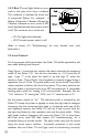
A Signatech II DS2431 Cut pin 3 of DS2431 8-Feb-2006 Rev: 1.0 A CON14 B C D J23 1 2 3 4 5 6 7 8 9 10 11 12 13 14 1 3 2 1 2 Note: Signatech II Chip and Loopback from pin 11 to 13 must be present for light to function. 3 SP069-WHIC3-001 Advanced Illumination 4 B C D 4 3 2 1 Figure 5: Output connector connection diagram example 4.2.5 Light Head: Power output is supplied through the 14 pin terminal block / connector on the back panel of the Pulsar 710.
Pulsar 710 Output Connector Pinout: Pin 1 2 3 4 5 6 7 8 9 10 11 12 13 14 Function Channel 1 supply: Positive Channel 1 return: Negative Channel 2 supply: Positive Channel 2 return: Negative Channel 3 supply: Positive Channel 3 return: Negative Channel 4 supply: Positive Channel 4 return: Negative Signatech 1: Identification Resistor 1 Signatech 1: Identification Resistor 2 Light head detection: Connects to Pin 13 Digital Ground Signatech II: EPROM data read/write Digital Ground: G
(Refer to section 6.0 “Troubleshooting” for more detailed error code information.) 4.4 Host Computer Control (REMOTE) If it is intended to operate the Pulsar 710 under Local Control skip to section 4.5 “Local Control”. To take full advantage of the flexibility of the Pulsar 710, software is provided which permits the operating parameters to be set by a host computer. The host computer will be connected to the Pulsar 710 via a USB port utilizing a USB Type B connector. (See Figure 6.
Figure 7: Software installation, destination folder Figure 8: Software installation, program group 4.4.2 Running under Host Computer Control 4.4.2.1 Configure Pulsar 710: Set the power switch on the Pulsar 710 to the “off” position. Using Figure 1, locate the four section dip switch that sets the operating mode. Set the four switches to 0000 (MODE 0). Logic “1” is set when the switch is up and Logic “0” is set when the switch is down.
4.4.2.2 Launch Pulsar 710 Controller Utility: To run the program; go to Start -> Programs -> Advanced Illumination -> Pulsar Controller. Upon execution of the Pulsar Controller Utility program, the dialog box shown in figure 9 will appear. 4.4.2.3 Pulsar 710 Utility Dialog Box Status Indicators: 4.4.2.3.1 Main Power: A green light and “ON” indicate the main power switch on the Pulsar 710 is turned on. Otherwise there will be a red light and “Off”.
command. The bottom panel shows information about the Pulsar 710. 4.4.2.4 Pulsar 710 Utility Dialog Box Output Controls: 4.4.2.4.1 Select Channel: The buttons labeled 1, 2, 3, and 4 select which channel the settings are to apply to. Synchronize and Equalize options can be selected by checking the appropriate box. • Synchronize: When this box is checked, any change in the settings for the selected channel are added to the three unselected channels.
• Test: The Pulsar 710 outputs pulses at 10 hertz. The current and timing are determined by the control settings. 4.4.2.4.4 Control Settings: There are three parameters that can be set to control the output of the Pulsar 710. • Current: The current setting determines the brightness of the light output. • Pulse Width: This is the length of the output pulse in microseconds. • Delay: This is the time in microseconds, between detection of a trigger signal and the start of the output pulse.
these two controls. 4.5.1.1 Mode Control: The mode control consists of a 4 position dip switch. Its range is 0 (0000) to15 (1111). See Table 2 for the definition of the modes. The down position is logic “0”, and the up position is logic “1”. PULSAR 710 FRONT PANEL CONTROLS 100's 1 2 3 10's 1 4 0 5 9 8 7 6 2 3 1's 1 4 0 5 9 8 7 6 MODE 2 3 8 7 4 0 5 9 6 1 2 3 4 Figure 10: Front panel controls 4.5.1.
Table P u l2:sLocal a r control 7 1 0 operating M a n umodes al 23 0110 0111 1000 1001 1010 1011 Constant Mode with percent of maximum current adjustment. Constant Mode with percent of maximum current adjustment, trigger acts as on/off. Leading rising edge triggered, width controlled by trigger falling edge or maximum allowed pulse width, whichever comes first. Leading falling edge triggered, width controlled by trigger rising edge or maximum allowed pulse width, whichever comes first.
Notes: Operational Mode is determined on startup or when a new lighthead is attached, rotary switches are active during operation Switch Settings: 0 - Down or Closed, 1 - Up or Open EE - Internal Electrically Erasable Programmable Read Only Memory (EEPROM) used to store Pulsar configuration information PC - Remote computer attached to Pulsar via USB interface Reserved locations available for future operation modes Only one of the four possible trigger inputs can be selected. Table 2 (continued) 3.
Table 3: Pulsar 710 trigger connector, pin description The wiring of the trigger input is dependent upon the trigger source. Sources can be either “Sourcing” or “Sinking” or both. A sourcing output (Sometimes referred to as “Pull Up”) provides an output voltage and must be connected to a sinking input. A sinking output (sometimes referred to as “Open Collector” or “Pull Down”) sinks current and must be connected to a sourcing input.
Note: Output Channel 4 can be independently triggered from Output Channels 1, 2, and 3. To independently trigger channel 4 take the following steps in the Pulsar 710 controller utility dialog box. 1. 2. 3. 4. 5. 6. Ensure Synchronize and Equalize are both un-checked. Select channel 4. Select the trigger for channel 4. Select channel 1, 2, or 3. Select the trigger for channels 1, 2, and 3. Click the program button for the new settings to become active.
- Trigger 1 and Trigger 2 can be configured as one RS232/485 logic compliant differential trigger. Trigger 1 and Trigger 2 can be configured to “pass through” to Trigger 3 and/or Trigger 4 respectively. Trigger 1 can be configured as a sinking input, single ended. Note: Triggers 2, 3, and 4 can be configured at the factory as a single ended sourcing input if required. However the configurations of these trigger inputs cannot be changed by the user in the field.
Timing bypass can also be activated in remote control via the host computer. Refer to Figure 6 for the Pulsar 710 controller dialog box. 1. In the mode section, pick Timing Bypass. 2. In the edge section, pick Rising or Falling. 3. Set the desired current level. 4. Click the program button for the new settings to become active. Section 5.0 Custom Programming For those needing to develop a custom interface to control the Pulsar 710, please consult Technical Support at Advanced illumination. Section 6.
the operator should contact Technical Support at Ai. 6.2 Error Codes The codes are listed below in bold face with a description of the fault indicated and a corrective action. 351 No lighthead detected. Corrective action – Be sure lighthead is plugged in to output connector. Check wiring of lighthead to connector. 352 Signatech I ID1 resistance not within known range. Corrective action – Verify that lighthead is equipped with Signatech I. Check wiring of lighthead to connector.
Section 7.0 Specifications Weight 3.8LB / 1.7kg Overall Dimensions 7.60” x 7.38” x 2.04” 193.1mm x 187.3mm x 51.
User Interface (continued) Power Switch (Rocker on/off) 4 Position Edge Accessible Piano Selects Mode - Pulse, Continuous, Style DIP Switch Percentage, TBD Outputs 3 LEDs (Power, Controller Status, Error) Power - Green, Controller Status - Amber, Error - Red Single Ended 0-30V (1K Load) External Interfaces Trigger (Electrical) Differential (Logic levels compliant with RS232/485 Protocol - AC Termination) Timing Bypass (Pulse width controls timing) Active High or Active Low (illumination is present wh
Specifications (continued) Light Heads (Electrical) Signatech II Compatible (Mech) 14 Position header (5.08mm Phoenix Terminal Block) 32 Backwards compatible with Signatech I with an AI supplied adapter cable a d v a n c e d i l l u m i n a t i o n .
Section 8.0 Appendix Appendix A: NPN / PNP PLC trigger connection The wiring of the trigger input is dependent upon the trigger source. Sources can be either “Sourcing” or “Sinking” or both. A sourcing output (Some times referred to as “Pull Up”) provides an output voltage and must be connected to a sinking input. A sinking output (sometimes referred to as “Open Collector” or “Pull Down”) sinks current and must be connected to a sourcing input.
D C 1 PLC PNP Sinking Output PNP PNP Sourcing Output PLC Pulsar 710 2 Trigger Connector Pin 1 Pin 2 Pin 3 Trigger Connector Pin 1 Pin 2 Pin 3 Pulsar 710 2.
Appendix B: Activate Differential Trigger 1. 2. Disconnect all input and output cable connections from the Pulsar 710. Remove the four retaining screws and gently lift the cover from the housing, taking care to clear the power switch. Note: ESD procedures should be followed while the cover is removed. It is recommended to use small tools, not fingers, to make Jumper or Switch changes. Figure 13: Pulsar 710 PCB 3. 4. 5. 6. 7. 8.
9. Trigger Pins 1 and 2 are now configured to recognize a RS232/485 logic level trigger input signal.
Appendix C: Activate Trigger Pass Through 1. Disconnect all input and output cable connections from the Pulsar 710. 2. Remove the four retaining screws and gently lift the cover from the housing, taking care to clear the power switch. Note: ESD procedures should be followed while the cover is removed. It is recommended to use small tools, not fingers, to make Jumper or Switch changes. 3. Switch S1 and Jumper J13 are used for these alternate trigger configurations. Figure 14 shows the location of S1 and J13.
9. Replace the cover on the housing, taking care to clear the power switch. Re-install the four retaining screws. 10. Reconnect all cables to the Pulsar 710 11. Trigger Pins 1 and 2 are now configured to “pass through” the trigger signals and output them on trigger pins 4 and 5 respectively.
193.1 (7.60) 34.1 (1.34) 119.1 (4.69) 187.3 (7.38) M6 NUT CHANNEL 114.3 (4.50) 50.8 (2.00) 5 51.8 (2.04) MOUNTING SURFACE 4 Pulsar 710 Manual UNIT MUST BE INSTALLED IN SUCH A WAY AS TO PROVIDE ADEQUATE AIR FLOW TO ENSURE AGAINST OVERHEATING. UNIT MAY BE MOUNTED IN ANY POSITION. UNIT WEIGHT: 3.8LB / 1.7 KG 2. 1. 2 INCHES MINIMUM SPACE REQUIRED FOR POWER / TRIGGER / COMMUNICATION CABLE INSTALLATION. ENSURE ADEQUATE SPACE IS AVAILABLE FOR ROTARY SWITCH / DIP SWITCH ADJUSTMENT IF REQUIRED. 4.
a d v a n c e d i l l u m i n a t i o n .