
Operator`s manual


a d v a n c e d i l l u m i n a t i o n . c o m
P u l s a r 7 1 0 M a n u a l
Operational Mode is determined on startup or when a new lighthead is attached, rotary
switches are active during operation
Switch Settings: 0 - Down or Closed, 1 - Up or Open
EE - Internal Electrically Erasable Programmable Read Only Memory (EEPROM) used to store
Pulsar configuration information
PC - Remote computer attached to Pulsar via USB interface
Reserved locations available for future operation modes
Only one of the four possible trigger inputs can be selected.
Notes:
24
3. Percentage Mode: The operator can select between constant and
gated DC modes. The rotary switches will control the current as a
percentage of the maximum current that Signatech II calculates for
the light head. 100% is the maximum setting.
a. 1’s switch = 1%
b. 10’s switch = 10%
c. 100’s switch = 100%
4. Timing Bypass Mode: This is another variation of the pulse mode,
where the operator can select between rising and falling edge trigger
signals. The rotary switches will control the current up to a maximum
of 9.99A per channel.
a. 1’s switch = 10mA
b. 10’s switch = 100mA
c. 100’s switch = 1A
Note: Signatech I and II will protect light heads from being over driven.
Therefore when maximum values of pulse width and/or current are
reached, rotation of the switches beyond these values does not result
in increased output.
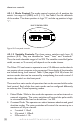
4.6 External Trigger Interface
The Pulsar 710 can accept up to 4 single ended TTL/CMOS input triggers,
or 1 differential RS232/485 logic level input trigger. The differential trigger
would typically be used when excessive noise and EMI could be present in
theinstallationareaorwhenlongtriggerlinesarerequired.ThePulsar710
canalsobeconguredto“passthrough”triggersignalssothatmultiple
devices can be triggered from one trigger signal. Ai recommends using
shielded,twistedpaircableforthetriggerinputs.Table3identiesthe
“standard” function of each pin within the two external trigger interface
connectors on the front panel of the Pulsar 710 as shipped from the
factory.
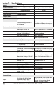
Table 2 (continued)