
Operator`s manual


a d v a n c e d i l l u m i n a t i o n . c o m
P u l s a r 7 1 0 M a n u a l
25
The wiring of the trigger input is dependent upon the trigger source.
Sources can be either “Sourcing” or “Sinking” or both. A sourcing output
(Sometimes referred to as “Pull Up”) provides an output voltage and must
be connected to a sinking input. A sinking output (sometimes referred to
as “Open Collector” or “Pull Down”) sinks current and must be connected
to a sourcing input. An output that is both sourcing and sinking can be
connectedto anytypeof input. Sometimesoutputs arecategorized as
NPN or PNP. Usually sinking outputs are NPN and sourcing outputs are
PNP. It is more important to know whether the output is sourcing or
sinking than whether it is NPN or PNP.
Refer to Appendix “A” for common “sourcing” and “sinking” connection
schematics.
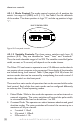
Figure 11 is a connection diagram for the Trigger Input connector. After
setting the power switch to the “OFF” position, connect an external
trigger in accordance with this diagram.
Trigger selection is performed using a host computer and the Pulsar 710
software. By default, trigger channel no. 1 is active when received from
the factory.
Inthesingle-endedtriggerconguration,theinputwillacceptTTL/CMOS
compatible signals and is internally clamped so that trigger inputs of up
to 30 V may be applied. If the differential trigger connection is chosen,
thePulsar710 willrecognizeinputlogiclevelsthatarecompliantwith
RS232/485 protocol. For all triggered modes, the trigger signal should
have a minimum width of 2 microseconds and a rise and fall time of less
than 200 nanoseconds.
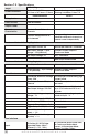
Table 3: Pulsar 710 trigger connector, pin description