
Operator`s manual


a d v a n c e d i l l u m i n a t i o n . c o m
P u l s a r 7 1 0 M a n u a l
Note: Output Channel 4 can be independently triggered from Output
Channels 1, 2, and 3. To independently trigger channel 4 take the
following steps in the Pulsar 710 controller utility dialog box.
1. EnsureSynchronizeandEqualizearebothun-checked.
2. Select channel 4.
3. Select the trigger for channel 4.
4. Select channel 1, 2, or 3.
5. Select the trigger for channels 1, 2, and 3.
6. Click the program button for the new settings to become active.
If the Pulsar 710 is being operated by local control, use the mode setting
dip switches discussed earlier, to set the mode to 0010 (Mode 2) for
positive edge triggering or 0011 (Mode 3) for negative edge triggering.
Set the power switch to “on”. The light head should now turn on with
each trigger pulse. Again, during local control operation, the pulse width
may be controlled with the rotary switches, and Signatech will set the safe
operating current. In this mode, the maximum pulse repetition rate is 200
pulses per second.
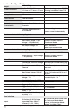
4.6.1 Alternate Trigger Congurations: Alternate trigger
congurations are possible by changing switch settings and/or jumper
positions inside the Pulsar 710. Below is a summary of the possible
alternatecongurations.
100's 10's 1's MODE
USB
RS232/485
EXTERNAL TRIGGER
VDC INPUT
POWER
ERROR
STATUS
POWER
+
-
1 2
3
4
5
6
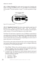
TRIG IN_3
TRIG IN_4
TRIG IN_1d
TRIG IN_2d
GND
NOTE:
1. IND I V I D U A L TRIG G E R I NPUTS ( P I N S 1, 2, 4 & 5 ) ARE S I N G L E ENDE D ( N O R MAL OP E R AT I O N )
2. PIN S 3 & 6 ARE C O M M O N GND
3. INP U T S 1 d & 2d ( P I N S 1 & 2 ) C A N BE USE D T O G ETHER T O P R O V I D E A SING L E D I F FERENT I A L I N PUT
(T W I S T E D PAIR) WHE N R E Q U IRED
4. TRI G G E R PA S S T HROUG H : P I N 1 = T R I G IN 1, P I N 4 = TRIG O U T 1
PIN 2 = T R I G IN 2, P I N 5 = TRI G O U T 2
0
1
2
3
4
5
6
7
8
9
8
7
0
4
3
2
1
5
9 6
7
8
1
2
3
4
5
0
9 6
1
2
3 4
0
1
Figure 11: Trigger connection diagram
26