
Operator`s manual


a d v a n c e d i l l u m i n a t i o n . c o m
P u l s a r 7 1 0 M a n u a l
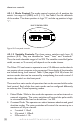
- Trigger 1 andTrigger 2 can be congured as one RS232/485 logic
compliant differential trigger.
- Trigger1andTrigger2canbeconguredto“passthrough”toTrigger
3 and/or Trigger 4 respectively.
- Trigger1canbeconguredasasinkinginput,singleended.
Note:Triggers2,3, and4 canbe congured atthe factoryas asingle
endedsourcinginputifrequired.Howeverthecongurationsof
thesetriggerinputscannotbechangedbytheuserintheeld.
Note: If the Pulsar 710 will be triggered by a PLC refer to Appendix “A”
forschematicsdepictingdifferentPLCcongurations.
Note: If differential trigger operation is desired, internal dip switch
activationandjumperplacementarerequired.ConsultAppendix
“B” for procedures to activate this feature.
Note:Iftriggerpassthroughisrequiredorifyouwanttochangetrigger
1 to sinking, internal dip switch activation is required. Consult
Appendix “C” for procedures to activate these features.
4.7 Timing Bypass
The Pulsar 710 may be set to track the pulse width of the trigger pulse.
If the selected trigger is set to falling edge the output is inverted. This
feature can be accessed in either remote or local operation. Local control
of the timing bypass feature can be activated by performing the following
steps.
1. Set the Pulsar 710 power switch to “OFF”.
2. Set the mode switch on the front panel to:
a. 1000 – Mode 8, Timing Bypass Positive edge trigger.
b. 1001 – Mode 9, Timing Bypass Negative edge trigger.
3. Set the Pulsar 710 power switch to “ON”.
The output pulse width will now track the pulse width of the
trigger pulse unless the maximum allowed pulse width for the
selected current is reached, at which point increasing the pulse
width of the trigger pulse will have no effect.
In this mode, the rotary switches set the current level. The “1’s” digit is in
10mA steps, the “10’s” digit is in 100mA steps, and the “100’s” digit is in
1A steps. 9.99A is the max selectable current in this mode.
27