
Operator`s manual


a d v a n c e d i l l u m i n a t i o n . c o m
P u l s a r 7 1 0 M a n u a l
Appendix B: Activate Differential Trigger
1. Disconnect all input and output cable connections from the Pulsar
710.
2. Remove the four retaining screws and gently lift the cover from the
housing, taking care to clear the power switch.
Note: ESD procedures should be followed while the cover is removed.
Itisrecommendedtousesmalltools,notngers,tomakeJumper
or Switch changes.
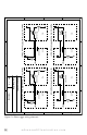
3. Switch S1 and Jumper J13 are used for these alternate trigger
congurations.Figure13showsthelocationofS1andJ13.
4. Place J13 so that pins 1 and 2 are shunted.
5. Verify that S1 POS 4 is “OFF”. POS 1 and 2 can be either “ON” or
“OFF”.
6. Additional Filtering can be activated on the differential trigger input
by turning S1 POS 3 to “ON”.
7. Replace the cover on the housing, taking care to clear the power
switch. Re-install the four retaining screws.
8. Reconnect all cables to the Pulsar 710
35
Figure 13: Pulsar 710 PCB