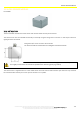
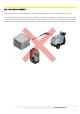
SHOCK SENSOR MODULE 22 SHOCK SENSOR MODULE P LX SEN SK 22.1 INSTALLATION The shock module includes the shock sensor that must be fitted correctly on the vehicle. The shock sensor must be installed horizontally or vertically using the fixing bores in the box. In this way the device is rigidly joined to the vehicle. Fixing bores: Ø 4.2 mm. Screws to be used: M4. The device should be installed with the cablegland turned downwards. The shock sensor must NOT be installed in a damped section of the vehicle (e.
SHOCK SENSOR MODULE 22.2 VISUALISATION With this device, the system can acquire the three components of the acceleration vector (Ax, Ay, Az) that will be used to determine whether a shock was detected or not. The icon of the SHOCKS module is green: the system is receiving data from the sensor. The icon of the SHOCKS module is red: the system is not receiving data (communication error or a problem in the sensor itself).
SHOCK SENSOR MODULE 22.3 CONFIGURATION To adjust the speed sensor, configure the settings in the 'SENSORS SEARCH' sub-menu in the 'SENSORS CONFIGURATION' menu. These are the options in the 'Sensor search' submenu: MOVE SENSORS: It defines active sensors. SHOCK SENSOR: It configures the shock sensor. Press the 'SHOCK SENSOR' key and access the configuration menu.
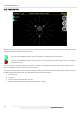
SHOCK SENSOR MODULE This screen displays the current value of the sensor (Value) and also allows setting the thresholds for the three axes (THR). Thresholds are always referred to the average value. Therefore, the shock is determined as a sudden variation in reference to the average. Ax, Ay and Az can have values of about ±8192, and depend on how the sensor is oriented in reference to the surface. If the sensor is placed over a surface, the vector related to that direction is about 1 g (2048).
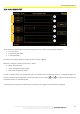
SHOCK SENSOR MODULE 22.4 SHOCK SENSOR TEST A B C A B C A B C Access the menu of test of the sensor by pressing 'Sensor Test'. 3 values are reported for each axis: A: current value B: maximum peak width C: threshold (THR) If a shock occurs, value B becomes red and an alarm sound is triggered.
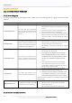
MAINTENANCE 23 MAINTENANCE 23.1 SOLVING COMMON PROBLEMS 23.1.1 Sensors diagnosis If an error is detected by the self-diagnosis of the system, refer to the following table as a guide on how to solve the problems. Error detected Description Possible solution Communication Error The CPU does not communicate with the HUB or the HUB does not communicate with one or more sensors.
MAINTENANCE Device Description Possible solution Does not turn on CPU The stand-by function does not work It restarts repeatedly Check the power supply; if it is higher than 30V, the CPU goes into protection mode to avoid any damage. Check the fuse inside the CPU. If the error does not disappear, we recommend contacting the support centre. Check the VQ. signal If the error does not disappear, we recommend contacting the support centre.
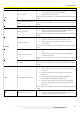
MAINTENANCE 23.2 RECOMMENDED CHECK INTERVALS Although there is a self-diagnostics for the system, before using the vehicle, always conduct a quick visual inspection of the condition of the components, in particular the sensors and their connection cables, which are the elements highly subject to damage caused by impacts or improper use of the vehicle. It is also advisable to conduct a more thorough checking of the system periodically by following the procedure shown in the table below.
23.3 CLEANING COMPONENTS To clean the display, do not use aggressive products that could damage the surface of the panel and the housing. To clean the devices found outside the vehicle, in particular the sensors and the HUB, it is advisable not to use direct jets of pressurised water (e.g., pressure washer). However, avoid aiming the jet directly to the connection area of the cables and the union between the cover and the housing; in any case keep a safe distance of at least 1 meter from these devices.
WIRING DIAGRAMS 24 WIRING DIAGRAMS 24.1 CABLES OF SENSORS 118 The technical materials and information contained in this document are strictly confidential and the exclusive property of Advanced Microwave Engineering s.r.l. These materials and information are intended solely for the purpose designated and may not be used otherwise. It is not permitted to disclose or reproduce them in whole or in part without express written permission.
WIRING DIAGRAMS 24.2 SAFE MOVE CPU CONNECTION The technical materials and information contained in this document are strictly confidential and the exclusive property of Advanced Microwave Engineering s.r.l. These materials and information are intended solely for the purpose designated and may not be used otherwise. It is not permitted to disclose or reproduce them in whole or in part without express written permission.
WIRING DIAGRAMS 24.3 HUB-SENSORS CONNECTION 120 The technical materials and information contained in this document are strictly confidential and the exclusive property of Advanced Microwave Engineering s.r.l. These materials and information are intended solely for the purpose designated and may not be used otherwise. It is not permitted to disclose or reproduce them in whole or in part without express written permission.
WIRING DIAGRAMS 24.4 SENSORS CONNECTION The technical materials and information contained in this document are strictly confidential and the exclusive property of Advanced Microwave Engineering s.r.l. These materials and information are intended solely for the purpose designated and may not be used otherwise. It is not permitted to disclose or reproduce them in whole or in part without express written permission.
WIRING DIAGRAMS 24.5 SAFE MOVE POWER DISTRIBUTION 122 The technical materials and information contained in this document are strictly confidential and the exclusive property of Advanced Microwave Engineering s.r.l. These materials and information are intended solely for the purpose designated and may not be used otherwise. It is not permitted to disclose or reproduce them in whole or in part without express written permission.
WIRING DIAGRAMS 24.6 SAFE MOVE POWER DISTRIBUTION (HIGH VOLTAGE BATTERY) The technical materials and information contained in this document are strictly confidential and the exclusive property of Advanced Microwave Engineering s.r.l. These materials and information are intended solely for the purpose designated and may not be used otherwise. It is not permitted to disclose or reproduce them in whole or in part without express written permission.
WIRING DIAGRAMS 24.7 Wi-Fi MODULE CONNECTION 124 The technical materials and information contained in this document are strictly confidential and the exclusive property of Advanced Microwave Engineering s.r.l. These materials and information are intended solely for the purpose designated and may not be used otherwise. It is not permitted to disclose or reproduce them in whole or in part without express written permission.
WIRING DIAGRAMS 24.8 CELLULAR MODEM CONNECTION The technical materials and information contained in this document are strictly confidential and the exclusive property of Advanced Microwave Engineering s.r.l. These materials and information are intended solely for the purpose designated and may not be used otherwise. It is not permitted to disclose or reproduce them in whole or in part without express written permission.
WIRING DIAGRAMS 24.9 BADGE READER CONNECTION 126 The technical materials and information contained in this document are strictly confidential and the exclusive property of Advanced Microwave Engineering s.r.l. These materials and information are intended solely for the purpose designated and may not be used otherwise. It is not permitted to disclose or reproduce them in whole or in part without express written permission.
WIRING DIAGRAMS 24.10 HUB EXTENSION (UP TO 8 SENSORS) The technical materials and information contained in this document are strictly confidential and the exclusive property of Advanced Microwave Engineering s.r.l. These materials and information are intended solely for the purpose designated and may not be used otherwise. It is not permitted to disclose or reproduce them in whole or in part without express written permission.