
Installation Instructions
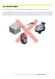

SHOCK SENSOR MODULE
110
The technical materials and information contained in this document are strictly confidential and the exclusive property of Advanced Microwave Engineering s.r.l.
These materials and information are intended solely for the purpose designated and may not be used otherwise.
It is not permitted to disclose or reproduce them in whole or in part without express written permission.
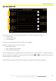
22.2 VISUALISATION
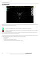
With this device, the system can acquire the three components of the acceleration vector (Ax, Ay, Az) that will be used to
determine whether a shock was detected or not.
The icon of the SHOCKS module is green: the system is receiving data from the sensor.
The icon of the SHOCKS module is red: the system is not receiving data (communication error or a problem
in the sensor itself).
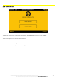
In case of a shock, the system warns the user with a sound and a message in red shown on the lower left-side corner,
which also displays the axis on which the shock occurred.
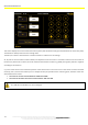
The system automatically saves the 100 measurements before the shock and the 100 measurements after the shock to
provide the dynamics of the event. The data related to the shocks recorded are:
Date and time
Intensity
Position on the map (if the GPS is active)
Vehicle speed (if the GPS or the speed indoor sensor is active)