
Installation Instructions
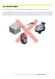

SHOCK SENSOR MODULE
112
The technical materials and information contained in this document are strictly confidential and the exclusive property of Advanced Microwave Engineering s.r.l.
These materials and information are intended solely for the purpose designated and may not be used otherwise.
It is not permitted to disclose or reproduce them in whole or in part without express written permission.
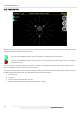
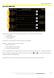
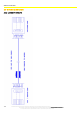
This screen displays the current value of the sensor (Value) and also allows setting the thresholds for the three axes (THR).
Thresholds are always referred to the average value.
Therefore, the shock is determined as a sudden variation in reference to the average.
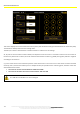
Ax, Ay and Az can have values of about ±8192, and depend on how the sensor is oriented in reference to the surface. If
the sensor is placed over a surface, the vector related to that direction is about 1 g (2048). The signal is positive or negative
according to the direction.
X, y and z values serve to check that the position of the shock sensor is the correct one. If the sensor has been mounted
correctly, that is, fixed to the vehicle (not in a damped section) and parallel to the anchoring point, the data of the axes
should follow these values:
The value of one axis must be between +1848 and +2048
The value of the other two axes must be between -200 and +200
The THR value is editable so it can be changed.