
Installation Instructions

SHOCK SENSOR MODULE
113
The technical materials and information contained in this document are strictly confidential and the exclusive property of Advanced Microwave Engineering s.r.l.
These materials and information are intended solely for the purpose designated and may not be used otherwise.
It is not permitted to disclose or reproduce them in whole or in part without express written permission.
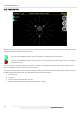
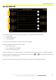
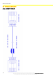
22.4 SHOCK SENSOR TEST
Access the menu of test of the sensor by pressing 'Sensor Test'. 3 values are reported for each axis:
A: current value
B: maximum peak width
C: threshold (THR)
If a shock occurs, value B becomes red and an alarm sound is triggered.
Moreover, a diagram is shown for each axis, in which:
White: real-time value
Green: average of the last samples
Red: lower and upper threshold
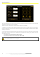
In order to display values in an appropriate scale, the software uses the 'Autoscale' function. To display the graph in a
position centred on the average value, and therefore easier to read, use the and keys. Each time the key is pressed,
the offset increases or decreases by 100.
'Stop' interrupts the capture; the 'Reset' key interrupts the recording process and deletes the diagram.
A
B
C
A
B
C
A
B
C