
User's Manual


Page 9
71423 56 8
CHANNEL
71 423 56 8
4. Function Settings
A. TRANSMITTER HANDSET
1. System Channel Settings
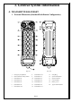
(Fig. 07)
Set the transmitter channel by adjusting the channel dip-switch located on the backside of the transmitter
encoder board (refer to Fig. 07 above). Only the first six (6) positions are used for channel programming
(refer to Fig. 08 below). The system channels table located on page 30 illustrates which dip-switch
setting corresponds to which channel. Once the transmitter channel is altered do make sure to change
receiver channel as well. The channel on both transmitter and receiver must be identical in order for
system to work. To change receiver channel please refer to page 21.
Example: Top slot → “1”
(Fig. 08) Bottom slot → “0”
The above dip-switch setting “1 0 0 1 0 0” corresponds to “channel 36” in the system channels table on
page 30.