
User's Manual

Flex 6ES/EX Instruction Manual
September 2016
Page 19 of 37
71 423 56 8
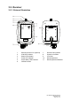
4.2. Receiver
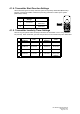
4.2.1. Receiver Channel Settings
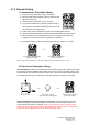
Set the receiver channel by configuring the channel dipswitch
located on the decoder board, only the first 6 dip positions are used
for channel programming. The system channels table on section
4.2.7 illustrates which dipswitch setting corresponds to which
channel. Once the receiver channel is altered do make sure to
change the transmitter channel as well. The channel on both
transmitter and receiver must be identical in order for the system to
work (refer to section 4.1.2 part B). When set to all zeros (000000),
the receiver becomes unassigned channel scheme (refer to section
4.1.2 part A).
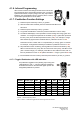
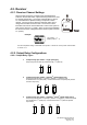
Example:
Top position → “1”
Bottom position → “0”
The above dipswitch setting “1 0 0 1 0 0” corresponds to “channel 36” in the system channels table
on section 4.2.7.
4.2.2. Output Relay Configurations
4.2.2.1. Output Relay Types
1. 2 output relays per motion – single speed only
Output relays with Forward (F) and Reverse (R) 1
st
speed only.
2. 3 output relays per motion – shared 2
nd
speed output relay
Output relays with Forward 1
st
speed (F1), Reverse 1
st
speed (R1) and
Forward/Reverse 2
nd
speed (F/R2). Forward and Reverse 2
nd
speed (F/R2) shared
the same output relay.
3. 4 output relays per motion – separate 1
st
and 2
nd
speed output relays
Output relays with Forward 1
st
speed (F1), Reverse 1
st
speed (R1), Forward 2
nd
speed
(F2) and Reverse 2
nd
speed (R2). Forward and Reverse 2
nd
speed are separate
output relays.