
User's Manual
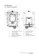
Flex 8ES/EX Standard, AB and Tandem Instruction Manual
September 2016
Page 17 of 42
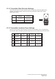
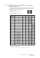
* A/1&2 ~ D/3&4 A/B pushbutton select function with designated LED indication.
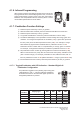
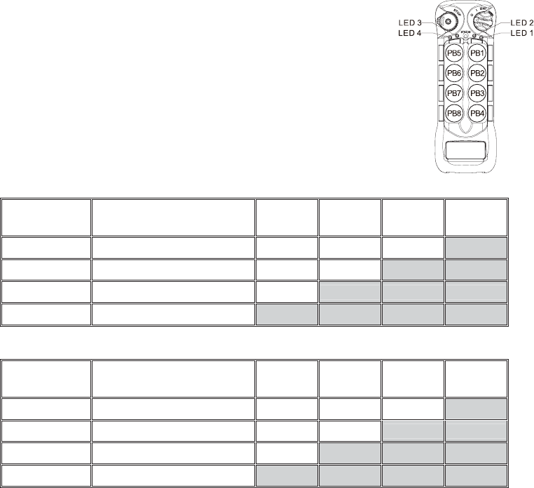
4.1.7.3. Toggled Pushbutton with LED Indication – Inline Top/Bottom
Pushbutton Configuration
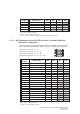
Set pushbutton toggled function (latching output relay) with
LED indications. LED 1 ~ 4 shown inside the shaded box
illustrates which LED on the transmitter lights up when the
designated pushbutton is pressed. Refer to section 4.2.4
JP4/JP5 inline jumper settings.
* PB1…PB8 Pushbutton number.
* Normal Normal momentary contact.
* LED 1 ~ LED 4 Pushbutton toggled function with designated LED indication.
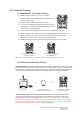
Function
Number
Display Type PB1 PB2 PB3 PB4
1
1 Red Normal Normal Normal LED 4
17
1 Green + 7 Reds Normal Normal LED 3 LED 4
18
1 Green + 8 Reds Normal LED 2 LED 3 LED 4
19
1 Green + 9 Reds LED 1 LED 2 LED 3 LED 4
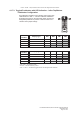
Function
Number
Display Type PB5 PB6 PB7 PB8
5
5 Reds Normal Normal Normal LED 4
20
2 Greens Normal Normal LED 3 LED 4
21
2 Greens + 1 Red Normal LED 2 LED 3 LED 4
22
2 Greens + 2 Reds LED 1 LED 2 LED 3 LED 4