
User's Manual

Flex 8ES/EX Standard, AB and Tandem Instruction Manual
September 2016
Page 20 of 42
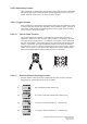
4.1.9. Display Frequency Band
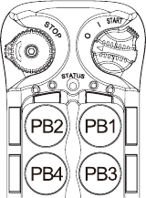
1) Rotate the power switch key to OFF ( 0 ) position.
2) With the STOP button elevated, press and hold PB1 and PB3
at the same time.
3) Rotate the power switch key to ON ( I ) position.
4) Let go PB2 and PB4 at the same time (entered Frequency
Band Display mode).
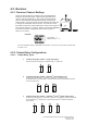
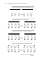
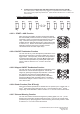
5) The Status LED displays the preset transmitter frequency band
with orange, green and red blinks. An orange blink represents
the hundreds (+100), a green blink represents the tens (+010) and a red blink
represents the units (+001). For example, 4 orange blinks followed by 3 green
blinks and 3 red blinks is 433MHz.
6) Exit Frequency Band Display mode by rotate the power switch key to OFF ( 0 ) position.
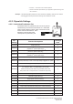
4.1.10. Output Feedback Settings
Up to 4 assignable relay outputs can be programmed into the system and feedback to the
transmitter LED indicators during operation. These settings require using the infrared IR
programmer unit. Please contact ARC representative for more details.
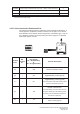
4.1.11. Infrared Function Settings
The transmitter is embedded with infrared sensors for infrared start function. These settings
require using the infrared IR programmer unit. Please contact ARC representative for more
details.
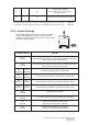
4.1.12. Zero-G Sensor Settings
The transmitter is embedded with a Zero-G sensor to guard against any unintended control of
the crane or equipment when transmitter is thrown or dropped. When triggered, the receiver
MAIN relays are deactivated with the exception of the horn output that can be assigned to any
of the Function output relays (K25, K26 or K30). This horn output setting requires the infrared
IR programmer unit. Please contact ARC representative for more details.