
User's Manual

Flex 8ES/EX Standard, AB and Tandem Instruction Manual
September 2016
Page 26 of 42
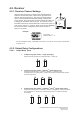
1 324 756 8
01100010
4 output relays Closed/Closed relay action + Brake + External warning*
4
01100100
3 output relays Closed/Closed relay action + Brake + External warning*
3
01100110
4 output relays Opened/Closed relay action + Brake + External warning*
4
* External warning function requires installing an external warning device such as horn and lights to
the K26 Function output relay.
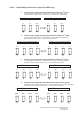
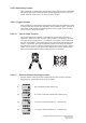
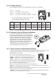
4.2.3.2. None-Interlocked Pushbutton Pair
Non-interlocked setting allows the pushbutton pair be pressed simultaneously. It
usually applies to equipment’s auxiliary functions such as lights, horn or buzzer.
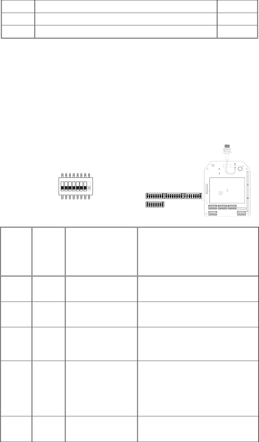
Each dipswitch on the decoder board corresponds to a pushbutton pair. Only the
first 7 dipswitch positions are used (counting from left to right), the 8
th
dipswitch
position (far right) is not used.
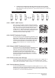
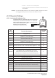
Function
Code
Dip
Position
#1
Dip Position
#2 ~ #4 (left button)
&
#5 ~ #7 (right button)
Function Description
A
1 000
Normal momentary contact
B
1 001
Toggled/latching contact (type A)
C
1 011
Toggled/latching contact (type B)
Output relay disconnects when STOP button is
pressed or transmitter power off
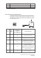
D
1 100
Normal + Start function
For added safety, must first rotate and hold
the power switch key at the START position
and then press the intended pushbutton to
activate the output relay
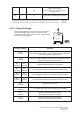
E
1 110
Pitch & Catch (type A)