
User's Manual

SDR Repeater
User Manual V0.4
Page | 11
3. SDR Overview
3.1 Switches & Fault Indicators
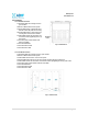
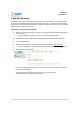
3.1.1 NMS and Module LED
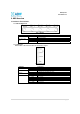
Figure 1: NMS LED
SDR-NMS Specifications
Solid Green NMS power is ON Power
OFF NMS is powered OFF
Solid Green Module has communication with NMS
Solid Red Module has a communication failure with NMS
CH-1, CH-2, CH-3,
CH-4
OFF Module is powered OFF
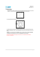
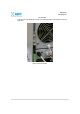
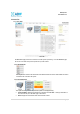
3.1.2 Module LEDs
SDR has LEDs on the front of the module as shown below in Figure 2.
Figure 1: Module LED
SDR-Module Specifications
Solid Green Module power is ON Power
OFF Module is powered OFF
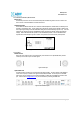
Solid Yellow Soft Fail alarm exist in the system Soft Fail
OFF No Soft Fail alarm are present in the system
Solid Red Hard Fail alarm exist in the system Hard Fail
OFF No Hard Fail alarms are present in the system
Input < -85dBm Zero (0) bar On
Input < -75dBm One (1) bar On
Input < -65dBm Two (2) bars On
Input < -55dBm Three (3) bars On
Input < -45dBm Four (4) bars On
RSSI
Input >= -45dBm Five (5) bars On