
User's Manual


SDR Repeater
User Manual V0.4
Page | 14
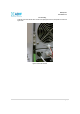
3.2.3 Ethernet Port and Host/Remote Switch
Ethernet Port
The Ethernet port can be used to communicate directly with the SDR using a RJ-45 crossover cable or can
also be used to connect the SDR to an external modem box.
Host/Remote Switch
The Host/Remote Switch allows the user to switch the default Repeater IP, Subnet Mask, and Gateway of the
repeater to an alternative setup. These settings can be adjusting by logging into the repeater in HOST mode
and configuring the settings under the Modem Box Setting section on the Install Page (section 4.4). Once the
settings are set, flipping the switch to the REMOTE position will reboot the repeater with the new alternate
settings. Please note that when the repeater is set to the REMOTE position, DHCP is disabled and the
repeater will not automatically assign an IP address to any device that connects directly to the repeater.
Figure 4: Ethernet Port and Host/Remote Switch
3.2.4 RF Ports
Module RF Ports
Donor and server antennas can be connected directly to the modules or the optional SDR-CHC (channel
combiner) can be used to split or combine signals.
Figure 5: RFU RF port
Optional SDR-CHC
An optional channel combiner can be mounted directly above the SDR. The donor portion of the SDR-CHC
can be used to split up a combine donor signal into PCS, BRS, and SMR. The server portion of the SDR-
CHC can be used to combine the server signals (PCS, BRS, 2.4 GHz WIFI, and SMR) into the Server Sum
port. Please contact sales@adrftech.com
if you are interested in purchasing the SDR-CHC.
Figure 6: Donor Combiner RF port