
User's Instructions


Pin8 EXT__IO_UF_OUT
Extend AF output
Pin9 EXT__ Ext_MIC
Extend MIC input
Pin10
+13v
12V_OUT 500mA_max
Pin11
IO_DX
DATAR peripheral equipment information
Pin12
IO_FSX
FSR sync output
Pin13
IO_CLKR
CLKR input signal
Pin14 Ext_BOOT0 Guidance enabled
Pin15
DG
Digital
Pin16
AG
Analog
Pin17 NDET_OUT
Expanding port (output)
Pin18 NDECT_IN
Expanding port (input)
Pin19
UART3_TX
UART3_TX serial port
Pin20
O_PTTO
PTT output
Pin21
IO_DR
DATAR peripheral equipment voice data
Pin22
IO_FSR
FSR signal lock input
Pin23
DG
Digital
Pin24
AG
Analogue
Pin25
RSSI_IN
Extension field intensity level(0~3V)(in)
Pin26
RSSI_OUT
Extension field intensity level(out)
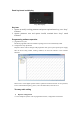
Repeater operation
turn on/turn off repeater
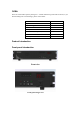
Press “power switch to the ”one” direction to turn on, then the speaker will make a sound, the
‘PWR’ indicator turning red, device start working, the system is going to stand by condition.
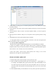
Audio, data transmit
Repeater receive the upstream RF signal, automatically control the transmitter (excitation module
and power amplifier module) to transfer, which will enhance the received signal to increase
communicate distance.
Indication of transit
1) ‘A’ and ‘B’ indicator turning light when device is working, indicate the signal is digital,TS1 is
during communication when ‘A’ turning light,TS2 is during communication when ‘B’ turning
light.
2) ‘TX’ and ’RX’ indicator turning light or ‘A’ and ‘B’ not turning light, indicate the signal is
analogue signal.