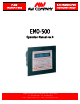
FLOW TRANSMITTERS ELECTRONICS FOR INSTRUMENTATION EMO-500 Operation Manual rev.4 8809 Industrial Drive, Franksville, WI 53126-9337 Tel: 262-884-9800 E-Mail: aw@awcompany.com Fax: 262-884-9810 Web: www.awcompany.
EMO 500 MANUAL TABLE OF CONTENTS Table of Contents.......................................................................................................................... 2 Overview of Display Screens ....................................................................................................... 3 Introduction................................................................................................................................... 4 Special Features ........................................
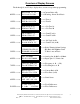
Overview of Display Screens The 0 through 9, and F1 keys display these screens except when programming. 0-KEY = = => RATIOA/B = 1.19 W=Y A=N I = 1.00 = = =>Current Ratio A/B = = =>Warning, Alarm, Ideal Ratio 1-KEY = = => FLW A=139.3 CCM FLW B=136.3 CCM = = = > Flow A = = = > Flow B 2-KEY = = => JOB A=10779. CC JOB B=11703. CC = = = > Job Total A = = = > Job Total B 3-KEY = = => GR A=300912. CC GR B=313391. CC = = = > Grand Total A = = = > Grand Total B 4-KEY = = => J A+B 614303.
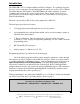
Introduction The EMO-500 is a Two Component Ratio and Flow Computer. It is primarily designed for use as a two component, ratio monitoring unit but can also be used as a Two Channel Flow Rate Monitor and Totalizer. The EMO 500 has the added capability of current (4-20mA) and voltage (0-5V) analog output signals. These outputs can be used as a representation of a selectable range of functions or in a ratio linked, closed loop mode Ratio Feedback Mode.
Special Features of the EMO-500 The EMO 500 is especially suited for use in dispensing systems with irregular flow patterns. The unit employs a user programmable sampling size to govern how often the ratio display is updated - the operator then has maximum control over the sampling period and can easily adjust this to suit his own system parameters. The user is often more interested in the ratio of components dispensed over a period of time, say in a batch, rather than on an instantaneous basis.
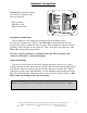
Hardware Connections Warning: The AC Power should be wired just as labeled on the three pin connector. PIN 1-Ground PIN 2-Line 110v. PIN 3-Line Neutral Grounding Considerations The grounding is a most important consideration in an installation where microprocessor technology is applied. The EMO-500 is a panel mounted unit and therefore the casing is connected to the sub-panel. If the sub-panel is metal it should be grounded.
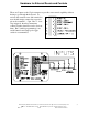
Hardware for External Resets and Controls There are 5 inputs to the 15 pin connector to provide extra control capability without having to go through the keyboard. To activate the external resets and controls the user should simply connect the respective pin to the common 1 - 5 pin. Pins 1 - 4 are edge triggered, therefore momentary contact switches should be used to activate them. Pin 5 (enable programming) is an on/off function and single pole toggle switch is recommended.
External Resets and Controls 1. Reset All This reset is the most powerful on the EMO 500. When activated it will reset: Ratio : A/B Job Vol A, Job Vol B & Job Vol A+B Warning & Alarm Limits Limits 3 & 4 Grand Totals Analog Outputs to start point 2. Scroll Display When activated, this input will scroll the display through all of the 11 screens available. It also allows access to the Quick Programming functions which are highlighted in red on the upper keypad line. (See pg 8.
The Quick Program Options While many programming variables such as KFR or meter selection may only require a "one time" setting - others may require some experimentation to find maximum efficiency settings. It may also prove desirable to allow an operator in the field some limited ability to make some quick adjustments. To accommodate these circumstances a method of jumping directly into some limited programming functions has been made available.
F1 Ratio Default Value = 1.00 This function is the address of the IDEAL RATIO which represents the desired ratio of FLOW A/FLOW B. The default is 1.00 which represents a 1 to 1 ratio. F2 Gate Time Default Value = 1.85 The GATE TIME is the period of time, in seconds, during which the flow rate calculation is made. The accuracy and response time of the flow rate display is therefore dependent upon this value. To achieve a 1% accuracy, the slowest pulse rate should deliver at least 100 pulses.
Programming the EMO 500 As a security precaution, access to the full programming section is only possible when pin 5 is "enabled". This can be accomplished by connecting pin 5, on the 15 pin connector, to the pin 6 Common (See Appendix D). Next, after first hitting F2, each function key, F1 through F6, will then allow access to the programming menu indicated immediately above it on the red banner strip (The banner strip is labeled 'PROGRAMMING' as indicated below).
The F1 key serves as an ESCAPE key to leave the programming functions and return to the last screen displayed. The F2 key will page the user through the programming options shown above AND IS REQUIRED TO ALLOW FURTHER ACCESS. The F3 key will call up Ratio Programming. < Enter the Ideal Ratio. This number represents the desired Ratio of Flow Amount A to Flow Amount B. The default is 1.00, meaning a 1 to 1 ratio. < Enter the Ratio Warning.
The F4 key will call up Limit Programming. OFF-RATIO WARNING & ALARM SETTINGS Since the EMO 500 is primarily a Ratio Monitor, Limits 1 and 2 are factory set to be triggered by an off-ratio condition. Default values are set at Limit 1 = Warning 5% and Limit 2 = Alarm 10%. For example: If the RATIO WARNING is programmed at +/- 10%, then the LIMIT 1 contact will close when this event occurs. LIMIT 2 will be similarly activated by the value programmed in the RATIO ALARM.
As mentioned previously, Limits 1 & 2 are preset for ratio alarms and are very easily adjusted for different ratio settings via the Quick Programming. Limits 3 & 4 can be used to warn of other monitored parameters such as flow rates or totalized fluid volumes. These settings can be adjusted as follows. There are three parts to the full Limit Programming section and each part should be done in order. They are: 1. Limit 3 Rule & value 2. Limit 4 Rule & value 3.
For example - Limit 1 & 2 can be programmed for Warning & Alarm settings on Flow A while Limit 3 & 4 could be allocated to Warning & Alarm for Flow B or Flow A+B and Total B respectively. Therefore Limits 3 and 4 can be selected independently but 1 & 2 cannot be separated. Therefore, if Ratio A/B is selected under the Limit 2 rule, the limit programming is complete. The unit will exit to the last display in memory before entering the programming mode.
The EMO 500 will flash "Direct Selection, Meter A or B" then the display will read "F2=A, F3=B, F4=A&B". This is where the user can choose the input the selected Flow Meter and Engineering Unit will be set. The display will the read "More Selections?, F2=Yes, F3=No". If both Flow Meters are programmed select F3, if not F2 will start the Meters/Units Program section again. NOTE: The Engineering Units for A and B should be the same.
F6 key will call up Global Programming. Global Default Values 1. KFR for A ----------- 100.0 2. KFT for A ----------- 10000 3. KFR for B ----------- 100.0 4. KFT for B ----------- 10000 5. Units for Rate ----------- 12 Hz 6. Units for Total ----------- 08 Impulses 7. Sample Size ----------- 200 Impulses 8. Gate Time ----------- 1.85seconds 9. Analog Offset ----------- 0000 10. Analog Gain ----------- 10200 11. Analog Rule ----------- 06 Ratio 12.
EXPLANATIONS OF THE GLOBAL VARIABLES 1. KFR for A.....Default 100.0 In order to make the EMO 500 display the correct rate in an engineering unit such as GPM, a scaling factor must be calculated. This Rate Scaling Factor is called the KFR. The KFR is calculated using the K-factor of the flow transmitter being monitored. The K-factor is the number of impulses per engineering unit established by a calibration test. For example: A flow meter could have a K-factor of 6304 imp/Gal.
2. KFT for A ................................................................................................Default 10000 In order to make the EMO 500 display the correct Totalized Value in Engineering Units, again the most important thing to know is the K-factor of the flow meter. The K-factor is the relationship between the amount of the impulses and the engineering units. In order to calculate the KFT for the EMO 500 apply the following formula.
5. Units for Rate. This variable will display the Engineering Units required for the flow rate display. This is strictly a display and does not perform the actual conversion of raw counted impulses. Those calculations are handled by the KFR. Enter the two digit number for the desired Units for Rate. 00 - cc/min 01 - liter/min 02 - gallon/min 03 - ounce/min 04 - RPM 05 - gram/min 06 - gram/sec 07 - lb/min 08 - Kg/min 09 - Kg/sec 10 - lb/sec 11 - lb/Hr 12 - Hz (Impulses/sec) 6. Enter Units for Total.
8. Gate Time ........................................................................................... Default 1.85 sec. The gate time (in seconds) is the amount of time pulses are accepted before flow rate calculations are performed. The accuracy and response time of the flow rate display are dependent on the gate time. To achieve a 1% flow rate accuracy, the lowest pulse rate should produce 100 pulses before the rate calculation is performed.
The Analog Output arrived at above should be a number from 0000-4095 which drives a D/A converter for a 4 - 20 mAmp and a 0 - 5 volt output on Pins 7 and 8 of the 9 Pin connector.
11. Analog Rule Default 06 The analog rule allows the user to set the analog output to follow any of the variables listed below. The variable is selected by entering its number as the Analog Rule. These are: 00 01 02 03 04 05 - Flow A Flow B Flow A+B Total A Total B Total A+B 06 - Ratio 07 - Ratio Feedback Mode 08 - Ratio w/Reset 09 - Ratio Feedback w/Reset 10 - A - B Job Total 11 - A - B Flow Rate NOTE: These variables will be used in the computations as numbers in Engineering Units.(ccpm,gals,ozs.
DEFAULT VALUES THROUGHOUT THE EMO 500 Ratio Programming Ideal Ratio.................................................................................................................. 1.00 Ratio Warning..............................................................................................................5% Ratio Alarm ...............................................................................................................10% Limit Programming Limit Rule 3..........................................
EMO 500 - RATIO FEEDBACK MODE The EMO 500 also features a Ratio Feedback Mode of operation in which the Ideal Ratio and the Actual Measured Ratio are compared and a 4-20 mA signal will be generated to control one of the Flow Rates. This will maintain the programmed Ideal Ratio over a wide range of flow rates. The formula used to determine the correct analog output is as follows: Analog Output = Half Range + (Ideal Ratio-Actual Ratio) * Gain The Half Range refers to the middle point of the Analog Output.
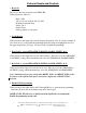
Serial Port Operations The EMO 500 has RS-232 and RS-485 serial port connections standard on the back panel 9 Pin connector. The user can connect this port to a host computer and then Read or Write to any memory location in the EMO 500. The RS-232 Pins on the 9 Pin connector are: Pin 3......TX transmit Pin 2......RX receive Pin 5......Ground The RS-485 connections are: Pin 6 ..... RX Pin 7 ..... TX Pin 8 ..... RX* Pin 9 .....
The answer received back from the EMO 500 will look like this: A03E36712XXcr ^...............all answers start with A ^^............low byte (at address 0F34) ^^..........next byte(at address 0F35) ^^........next byte(at address 0F36) ^^......high byte(at address 0F37) ^^....checksum ......carriage return ends the string The protocol format for writing to the EMO 500 is as follows: >01J03340F3587XXcr ^.....................start of string must use the > sign ^^..................unit number ^.................
To calculate the final checksum, convert the decimal number 493 into HEX (493=1EDh) and take the last two characters (ED) for the checksum. The final string would look like this: >01K0F3404EDcr Important points for serial communication 1. Serial communication will be disabled if the EMO-500 is in programming mode. 2. All characters in the communication string should be in CAPITALS. Example: >K= is ASCII 75 and will be recognized by the EMO-500, but >k= is ASCII 107 and will not be recognized. 3.
The bytes are always arranged such that the low byte is first and the more significant bytes follow. In the EMO-500, the least significant byte (LSB) is at the lower address. For example: If the data from the totalizer was read as 90D58901 the LSB is 90 and the MSB is 01.
ADDRESS INFORMATION IMPORTANT When writing to the EMO 500 there are always two locations to be changed for a permanent entry into the memory. This is because there are locations for data running currently in the RAM and there are locations for data that will be battery backed. If the information has been written to the running locations alone it will be lost when the EMO 500 is turned off.
Running Address in HEX Back-up Address in HEX Bytes Description 05F5 061A 0637 05FF 061C 0639 05F7 061E 063B 0601 0620 063D 050A 050C 050E 0510 060B 0604 0605 *0614 (4) 0618 0622 059D 05AA 05B9 0606 *053D 0626 0516 051A 051E 05B5 *05A0 *05A6 05EF *052E *0533 0504 05A4 0402 0404 0412 040A 040C 0414 0406 0408 0416 040E 0410 0418 042D 042F 0422 0424 042C 0429 042A 042 0420 041E 0437 0433 0431 041A 041C 042C read only read only read only read only read only read only read only read only read only read only
* These special variables indicated on the next page function in this manner. * Ideal Ratio- The largest number that can be written into the Ideal Ratio without an overflow is 640. Variable at address 0426h is 3 bytes, at 0614h is 4 bytes. * Job Total A (SD2)- This variable will show twice the amount read from the Job A display. This is because the number is actually a raw count from the freq. input. The number read will match the totals seen in the Status Display 2 screen.
LIMITED WARRANTY AW-Company warrants the EMO-500 Flow Computer to be in good working order for a period of 1 (one) year from the date of purchase from AW-Company or an Authorized AW-Company distributor. Should the EMO-500 fail to be good working order at any time during this 1 year warranty period, AW-Company will, at its option, repair or replace the EMO-500 at no additional change expect as set forth below.
AW Company 8809 Industrial Drive, Franksville, WI 53126 à web: www.awcompany.com Tel: 262-884-9800 Fax: 262-884-9810 | Email: aw@awcompany.com REV. 4 10/05 EMO-500 Manual.
AW Company 8809 Industrial Drive, Franksville, WI 53126 à web: www.awcompany.com Tel: 262-884-9800 Fax: 262-884-9810 | Email: aw@awcompany.com REV. 4 10/05 EMO-500 Manual.
AW Company 8809 Industrial Drive, Franksville, WI 53126 à web: www.awcompany.com Tel: 262-884-9800 Fax: 262-884-9810 | Email: aw@awcompany.com REV. 4 10/05 EMO-500 Manual.
AW Company 8809 Industrial Drive, Franksville, WI 53126 à web: www.awcompany.com Tel: 262-884-9800 Fax: 262-884-9810 | Email: aw@awcompany.com REV. 4 10/05 EMO-500 Manual.
AW Company 8809 Industrial Drive, Franksville, WI 53126 à web: www.awcompany.com Tel: 262-884-9800 Fax: 262-884-9810 | Email: aw@awcompany.com REV. 4 10/05 EMO-500 Manual.
AW Company 8809 Industrial Drive, Franksville, WI 53126 à web: www.awcompany.com Tel: 262-884-9800 Fax: 262-884-9810 | Email: aw@awcompany.com REV. 4 10/05 EMO-500 Manual.
AW Company 8809 Industrial Drive, Franksville, WI 53126 à web: www.awcompany.com Tel: 262-884-9800 Fax: 262-884-9810 | Email: aw@awcompany.com REV. 4 10/05 EMO-500 Manual.