
Operation Manual


Installation and Operation Manual S400 series 20
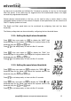
3.2.1. Mounting the Multi S400 unit
The Multi unit must be mounted in a visible location and protected from any risk of shocks. It
should be placed more than 10cm from a compass and more than 50cm from radio or radar
antenna, far from all engines, fluorescent light, alternators and radio or radar transmitters. It
should be accessible from the rear; minimum depth cabin side 50mm. The rear panel of the
unit should be protected from humidity. The mounting surface should be flat and of thickness
less than 20mm.
Drill a hole 50mm in diameter at the chosen location
Unscrew the nut located on the rear of the unit
Remove the adhesive protection around the unit
Insert and position the unit in the mounting hole
Screw back the nut
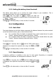
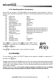
3.2.2 . Description of electrical connections
3.2.2.1. Bus connection
The bus link is provided by a 7-wire shielded cable, arranged as follows:
Red +12V DC
Black GND / NMEA (-) Input and Output
Orange bus
Yellow NMEA input (+)
White NMEA output (+)
Green Buzzer and external light
Blue NC
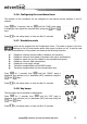
3.2.2.2. Speed connection
The connection with the speed sensor is provided by a 30 cm shielded cable, fitted with an 8-
pin connector with bayonet locking.
Connector pins:
1: Bare Ground
2: Red +12V DC
3: White Thermistor -
4: Brown Thermistor +
5: Yellow Sensor presence
6: Green Paddlewheel
7: Bare Sounder ground
8: Colourless Sounder excitation
This connection is used to connect a multifunction sensor: Speed/Sounder/Temperature
3.2.2.3. Sounder connection