I.O.M. #123 updated 04/10/2015 INSTRUCTION MANUAL • INSTALLATION • OPERATION • MAINTENANCE Covering models From 5 to 40 tons With ‘M1’ Instruments & Scroll Compressors Model: Serial Number : ADVANTAGE ENGINEERING, INC. 525 East Stop 18 Road Greenwood, IN 46142 317-887-0729 fax: 317-881-1277 Service Department fax: 317-885-8683 www.AdvantageEngineering.com E-mail service@AdvantageEngineering.
INSTRUCTION MANUAL M1 INSTRUMENT & SCROLL COMPRESSORS AIR & WATER-COOLED MODELS With COVERING INSTALLATION OPERATION MAINTENANCE ADVANTAGE ENGINEERING, INC. 525 East Stop 18 Road Greenwood, IN 46142 317-887-0729 fax: 317-881-1277 Service Department fax: 317-885-8683 Website: www.AdvantageEngineering.com E-mail: service@AdvantageEngineering.
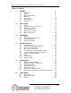
Maximum Series Portable Chiller : Air & Water-Cooled : M1 Series Instrument TABLE OF CONTENTS 1.0 GENERAL 1.1 Introduction 1.2 Safety 1.3 Receiving instructions 1.4 Efficiency 1.5 Clean air act 1.6 Water Treatment 1.7 Components 7 8 8 9 9 10 10 11 2.0 INSTALLATION 2.1 General 2.2 To and From process connections 2.3 Water supply connection 2.4 Air-cooled condenser 2.5 Water-cooled condenser 2.6 Electrical connection 13 15 15 15 15 17 18 3.0 OPERATIONS 3.
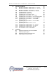
Maximum Series Portable Chiller : Air & Water-Cooled : M1 Series Instrument 7.0 RELATED DRAWINGS 7.1 Mechanical Schematic : Water-Cooled : 5 - 10 Tons 7.2 Mechanical Schematic : Water-Cooled : 15 - 40 Tons 7.3 Mechanical Schematic : Air-Cooled : 5 - 10 Tons 7.4 Mechanical Schematic : Air-Cooled : 15 - 30 Tons 7.5 Typical Electrical : Air-Cooled 7.6 Typical Electrical : Water-Cooled 7.7 Typical Physical : Air-Cooled : 5 Tons 7.8 Typical Physical : Air-Cooled : 7.5 - 10 Tons 7.
THIS PAGE INTENTIONALLY BLANK Page: 6
Maximum Series Portable Chiller : Air & Water-Cooled : M1 Series Instrument 1.0 GENERAL 1.1 1.2 1.3 1.4 1.5 1.6 1.7 1.8 INTRODUCTION SAFETY RECEIVING INSTRUCTIONS EFFICIENCY CLEAN AIR ACT MISCELLANEOUS WATER TREATMENT COMPONENTS ADVANTAGE ENGINEERING, INC. 525 East Stop 18 Road Greenwood, Indiana 46142 317-887-0729 Fax: 317-881-1277 Service Department Fax: 317-885-8683 Email: service@AdvantageEngineering.
Maximum Series Portable Chiller : Air & Water-Cooled : M1 Series Instrument 1.1 1.2 INTRODUCTION A. This manual covers portable chillers from 5 to 40 tons (17 to 140 kW) of cooling capacity using the Advantage M1 microprocessor control instrument and fixed displacement scroll compressors and digital scroll compressors. The standard fluid operating temperature range for this chiller is 20°F to 80°F for units using R410A refrigerant. Units using other refrigerants have different standard operating ranges.
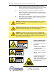
Maximum Series Portable Chiller : Air & Water-Cooled : M1 Series Instrument C. Observe all warning and safety placards applied to the chiller. Failure to observe all warnings can result in serious injury or death to the operator and severe mechanical damage to the unit. D. Observe all safety precautions during installation, startup and service of this equipment due to the presence of high voltage and refrigerant charge. Only qualified personnel should install, startup and service this equipment. E.
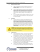
Maximum Series Portable Chiller : Air & Water-Cooled : M1 Series Instrument 1.3 1.4 RECEIVING INSTRUCTIONS A. Chillers are shipped skid mounted and wrapped in plastic prior to shipment. Check the overall condition of the equipment prior to accepting delivery. B. Check for visible damage and document any evident damage on the delivery receipt. Check the refrigerant gauges to be sure the system charge is intact. See the chart in section 8.
Maximum Series Portable Chiller : Air & Water-Cooled : M1 Series Instrument refrigeration service technicians performing work on this chiller must be licensed and certified. E. 1.6 Vent all refrigerant relief valves in accordance to ANSI/ASHRAE Standard 15. WATER TREATMENT A. The use of untreated or improperly treated water in a portable chiller may result in scaling, erosion, corrosion, algae or slime. B.
Maximum Series Portable Chiller : Air & Water-Cooled : M1 Series Instrument Bypass Pressure Gauges Insulated Reservoir Electrical Cabinet Water Regulator Valve Compressor Water-Cooled Condenser Coolant Pump Water-Cooled Model 10 ton unit shown. ABS fascia, top and enclosure panels removed for photo.
Maximum Series Portable Chiller : Air & Water-Cooled : M1 Series Instrument 2.0 INSTALLATION 2.1 2.2 2.3 2.4 2.5 2.6 2.7 GENERAL UNIT LOCATION TO AND FROM PROCESS CONNECTIONS MAKE-UP WATER SUPPLY CONNECTION AIR COOLED CONDENSER INSTALLATION WATER-COOL CONDENSER INSTALLATION ELECTRICAL CONNECTION ADVANTAGE ENGINEERING, INC. 525 East Stop 18 Road Greenwood, Indiana 46142 317-887-0729 Fax: 317-881-1277 Service Department Fax: 317-885-8683 Email: service@AdvantageEngineering.
Maximum Series Portable Chiller : Air & Water-Cooled : M1 Series Instrument 2.1 2.2 GENERAL A. Chillers are shipped skid mounted and wrapped in plastic prior to shipment. Check the overall condition of the equipment prior to accepting delivery. Check for visible damage and document any evident damage on the delivery receipt. Shipping damage is the responsibility of the carrier. B.
Maximum Series Portable Chiller : Air & Water-Cooled : M1 Series Instrument condenser coil if the panels are not in place. Starting the unit without all the enclosure panels in place will result in a high pressure refrigerant fault. 5. 2.3 Units with a motor-driven fan may not use duct work unless a booster fan of equal volume rating has been installed in the duct. TO AND FROM PROCESS CONNECTIONS A.
Maximum Series Portable Chiller : Air & Water-Cooled : M1 Series Instrument installed, all such devices must be open and clean during unit operation. 2.4 MAKE-UP WATER SUPPLY CONNECTION A. The automatic water make-up system continually monitors the reservoir tank and fills it when needed. Connect as follows: 1. B. Using appropriately rated hose or fluid piping connect the “water make-up” connection to the plant’s water source.
Maximum Series Portable Chiller : Air & Water-Cooled : M1 Series Instrument WARNING: Do not attempt to duct exhaust air from a portable chiller using motor driven fans. Exhaust air can only be ducted from a portable chiller using a blower assembly. a HVAC contractor should be consulted for sizing and material specifications. Exhaust air can not be ducted on motor mounted fan models. C. D.
Maximum Series Portable Chiller : Air & Water-Cooled : M1 Series Instrument F. Condenser Air Filtering. Use a filter that produces very low air flow restrictions. Generally a disposable fiberglass filter with a MERV rating of 2 - 3 provides adequate air filtration. The purpose of the filter is to prevent large particles such as dust, lint and debris from fouling the condenser. You should be able to see through the filter media.
Maximum Series Portable Chiller : Air & Water-Cooled : M1 Series Instrument D. The installation of a strainer in the condenser “water in” line is recommended. This removes solids from the water supply and serves to protect the water saver (regulator) valve. E. The water regulator valve (figure 2.5A) is normally factory set for proper operation.
Maximum Series Portable Chiller : Air & Water-Cooled : M1 Series Instrument power entry hole into the electrical cabinet. This allows the matching of the entry hole size and location to the customer supplied fittings. 5. A unit specific electrical drawing is shipped with the unit. 6. Voltage supplies must be within +/- 10% of the name plate voltage and must be within 2% from leg to leg.
Maximum Series Portable Chiller : Air & Water-Cooled : M1 Series Instrument Instrument Transformer Transformer: Line Voltage to 115 volts Terminal Strip Pump Starter Power Entry Terminal Block Pump Overload Block Pump & Transformer Fusing Ground Lug Compressor & Fan Contactor Grounding Bus Bar Figure 2.5A Typical electrical panel Electrical Panel ADVANTAGE ENGINEERING, INC.
THIS PAGE INTENTIONALLY BLANK Page: 22
Maximum Series Portable Chiller : Air & Water-Cooled : M1 Series Instrument 3.0 OPERATIONS 3.1 3.2 3.3 3.4 GENERAL START UP/OPERATIONS PROCEDURE INSTRUMENT SHUT DOWN ADVANTAGE ENGINEERING, INC. 525 East Stop 18 Road Greenwood, Indiana 46142 317-887-0729 Fax: 317-881-1277 Service Department Fax: 317-885-8683 Email: service@AdvantageEngineering.
Maximum Series Portable Chiller : Air & Water-Cooled : M1 Series Instrument 3.1 GENERAL A. Failure to follow the factory required operations procedure may adversely affect the unit’s ability to adequately control process temperature and may create a hazardous operating condition which may result in serious operator injury and/or unit damage. WARNING: Follow all Factory operations procedures.
Maximum Series Portable Chiller : Air & Water-Cooled : M1 Series Instrument See Section 6.3.J for more information. Please note, Sections 3.2.A & 5.4 are not applicable for reverse flow units. 3. WATER QUALITY CONTROL. Lack of, as well as, improper water treatment can damage the chilling unit. The services of competent water treatment specialist should be obtained and their recommendations followed.
Maximum Series Portable Chiller : Air & Water-Cooled : M1 Series Instrument B. PROPER ROTATION (PHASING) OF SCROLL COMPRESSORS & PUMPS & FANS 1. Correct compressor, fan (on air-cooled units) and pump rotation is critical for unit performance and to avoid severe damage to the compressor. 2. All portable chiller compressors and pumps will be set to rotate in the same direction during the testing process at the factory. 3.
Maximum Series Portable Chiller : Air & Water-Cooled : M1 Series Instrument WARNING: The electrical power is engaged at this point and caution must be observed while the electrical supply is engaged and cabinet panels are removed and opened. 7. Procedure to set proper rotation: a. Supply electrical power to the unit. Once the correct voltage is supplied to the unit, the POWER switch on the unit’s control panel will illuminate.
Maximum Series Portable Chiller : Air & Water-Cooled : M1 Series Instrument when viewed from the rear of the motor. If the shaft does not rotate when the ON/OFF SWITCH is on, the operator must identify the cause as outlined in the troubleshooting and repair section of this manual. f. 2. If the motor shaft is phased correctly (shaft turns in a clockwise direction), continue with step C.
Maximum Series Portable Chiller : Air & Water-Cooled : M1 Series Instrument maintenance. Since the evaporator in most liquid chillers is flow sensitive, the efficiency of operation is directly related to the flow of liquid. b. 2. 3. Maximum chiller efficiency is obtained at approximately 2.4 gpm per ton of rated capacity. Low liquid flow can reduce efficiency and in some cases allow ice to develop in the evaporator which can damage the evaporator.
Maximum Series Portable Chiller : Air & Water-Cooled : M1 Series Instrument of the valve. Turning the “T” handle or adjusting stem in the clockwise direction puts more pressure on the valve’s spring reducing bypass flow. Turning the “T” handle or adjusting stem counter clockwise puts less pressure on the spring and increases bypass flow. Adjust the “T” handle or adjusting stem until the low pressure gauge reading is in the normal operating range for the refrigerant type used in the chiller.
Maximum Series Portable Chiller : Air & Water-Cooled : M1 Series Instrument M1 Series Control. This control instrument is used on units with fixed displacement compressors. M1D Series Control. This control instrument is used on units with digital scroll compressors. Figure 3.3A water/glycol solution is mandatory to prevent freezing of the evaporator. Freezing may cause the evaporator to rupture allowing water and freon to mix which will cause major damage to the refrigeration system.
Maximum Series Portable Chiller : Air & Water-Cooled : M1 Series Instrument Lockout (SPL) jumper. Refer to Section 3.3.c.3 of this manual for more information. B. INSTRUMENT OPERATION 1. To start the unit, toggle on the illuminated ON/ OFF SWITCH. The pump will start and the chiller control will begin temperature control operations. 2. To select setpoint temperature, press and hold the UP ARROW or DOWN ARROW keys until the desired set point temperature is displayed in the TEMPERATURE WINDOW.
Maximum Series Portable Chiller : Air & Water-Cooled : M1 Series Instrument decrease (DOWN ARROW) the setpoint temperature. If the push button is pressed momentarily the setpoint value is incremented or decremented by one degree. If the push button is held down the setpoint will increase or decrease continuously. 3. SETPOINT LOCK OUT JUMPER: This jumper controls whether the user is allowed to reduce the setpoint below 48°F or 9°C.
Maximum Series Portable Chiller : Air & Water-Cooled : M1 Series Instrument on, the control has a 15 second buffer for the low pressure fault. If a low pressure condition occurs within the first 15 seconds, the control waits the amount of time specified by the “LP TIME” potentiometer before indicating an fault and turning off the compressor. If the condition is corrected before the time expires, no fault occurs.
Maximum Series Portable Chiller : Air & Water-Cooled : M1 Series Instrument 3. LOW PRESSURE GAUGE: Indicates refrigerant pressure on the suction side of the compressor. This pressure will fluctuate with the process temperature. WARNING: Follow all shut down procedures outlined in this manual. 3.4 SHUT DOWN/DISCONNECT SEQUENCE A. PRECAUTIONS/WARNINGS 1. B. The operator must follow all shut down procedures outlined in this manual.
THIS PAGE INTENTIONALLY BLANK Page: 36
Maximum Series Portable Chiller : Air & Water-Cooled : M1 Series Instrument 4.0 TROUBLESHOOTING 4.1 4.2 4.3 4.4 4.5 4.6 4.7 4.8 4.9 4.10 UNIT WILL NOT START COMPRESSOR HUMS BUT WILL NOT START SHUTS OFF ON HIGH PRESSURE SHUTS OFF ON LOW PRESSURE COMPRESSOR SHUTS OFF ON INTERNAL OVERLOAD LOW OR NO PROCESS PRESSURE OR WATER FLOW COOLING CAPACITY INADEQUATE SENSOR PUMPS CHILLER CONTROLLER ADVANTAGE ENGINEERING, INC.
Maximum Series Portable Chiller : Air & Water-Cooled : M1 Series Instrument WARNING: Before troubleshooting or servicing this unit, follow all company lock-out tag-out procedures. 4.1 4.2 4.3 UNIT WILL NOT START A. Power off. Check main disconnect. B. Main line open. Check fuses. C. Loose terminals. Tighten terminals with POWER OFF. D. Control circuit open. Check control voltage fuses and transformer. COMPRESSOR HUMS BUT WILL NOT START A. Contactor problem.
Maximum Series Portable Chiller : Air & Water-Cooled : M1 Series Instrument 2. B. Water-cooled units: 1. Water regulator valve. Adjust condenser water regulator valve to maintain 100°F to 105°F refrigerant condensing temperature*. If valve is defective, have valve repaired or replaced by a refrigeration serviceman. 2. The water regulator valve is normally factory set for proper operation.
Maximum Series Portable Chiller : Air & Water-Cooled : M1 Series Instrument * See Temperature-Pressure chart in Section 8.2 for refrigerant pressure. The low pressure switch is set to cut-out at 32°F and cut-in at 36°F - 39°F*. If a low pressure condition exists for more than five seconds the compressor will stop and a “L-P” fault will appear in the display window. After the refrigerant pressure rises above the cut-in pressure, a three minute time delay will occur before the compressor restarts.
Maximum Series Portable Chiller : Air & Water-Cooled : M1 Series Instrument during off cycle. Have the solenoid repaired or replaced if defective by a refrigeration serviceman. 4. 4.5 COMPRESSOR SHUTS OFF ON INTERNAL OVERLOAD A. 4.6 4.7 Expansion valve plugged or inoperative. Check thermal bulb and capillary tube for damage. Have repaired or replaced if defective by a refrigeration service man. Control does not reset.
Maximum Series Portable Chiller : Air & Water-Cooled : M1 Series Instrument 4.8 4.9 4.10 SENSOR A. The sensor is a solid state temperature transducer which converts temperature input to proportional current output. B. To quickly test for a defective probe, switch connections between the defective probe and a probe known to be working properly. A defective sensor will display a “---” in the display window on the instrument control.
Maximum Series Portable Chiller : Air & Water-Cooled : M1 Series Instrument 3. E. OUT-OF-WARRANTY SERVICE INCIDENT 1. Call Advantage Service at 317-887-0729 for diagnostic assistance. 2. If a control instrument is determined to be at fault, you will be referred to the instrument manufacturer, Advantage Electronics (an Advantage Engineering affiliated company). You have 3 options: 3. F. Return the defective instrument freight pre-paid for a full credit.
THIS PAGE INTENTIONALLY BLANK Page: 44
Maximum Series Portable Chiller : Air & Water-Cooled : M1 Series Instrument 5.0 MAINTENANCE 5.1 5.2 5.3 5.4 5.5 5.6 5.7 WARRANTY SERVICE PROCEDURE PERIODIC PREVENTATIVE MAINTENANCE SPECIAL MAINTENANCE SOLENOID VALVE SERVICE PUMP SEAL SERVICE CHECKING THE REFRIGERANT CHARGE PROPER CLEANING PROCEDURE FOR BRAZED PLATE EVAPORATOR ADVANTAGE ENGINEERING, INC. 525 East Stop 18 Road Greenwood, Indiana 46142 317-887-0729 Fax: 317-881-1277 Service Department Fax: 317-885-8683 Email: service@AdvantageEngineering.
Maximum Series Portable Chiller : Air & Water-Cooled : M1 Series Instrument 5.1 5.2 WARRANTY SERVICE PROCEDURE A. In the event of a problem with a chiller that can not be resolved by normal troubleshooting procedures, the customer is invited to consult the Service Department for assistance. The correct model number and serial number of the chiller must be available. The service department will attempt to isolate the problem and advise repair procedures.
Maximum Series Portable Chiller : Air & Water-Cooled : M1 Series Instrument 5.3 I. Refrigerant sight glass: Check for bubbles when compressor is operating at 100%. Check the moisture indicator for a color other than green. J. Clean unit. SPECIAL MAINTENANCE A. Any service of the refrigeration system must be accomplished by a certified refrigeration technician. 1. Addition of compressor oil. 2. Addition of refrigerant. 3. Repair of a refrigerant leak. 4. Adjustment of super heat. 5.
Maximum Series Portable Chiller : Air & Water-Cooled : M1 Series Instrument 5.4 AUTOMATIC WATER MAKE-UP SYSTEM SERVICE A. The automatic water make-up system consists of a level switch (figure 5.4A) and a solenoid valve (figure 5.4B). When the tank level is low the level switch signals the solenoid valve to open allowing make-up water to re-fill the tank. B. Level switch maintenance and service. C. 1. The level switch contacts engage and disengage the water make-up solenoid valve. 2.
Maximum Series Portable Chiller : Air & Water-Cooled : M1 Series Instrument d. The solenoid valve can be disassemble by removing the 4 retaining screws. e. Keeping all electrical connections intact, lift the coil and top solenoid base assembly and set aside. f. Note the arrangement of the core spring and core assembly, diaphragm spring and diaphragm assembly. (See diagram.) g. Clean all components as required.
Maximum Series Portable Chiller : Air & Water-Cooled : M1 Series Instrument 5.5 PUMP SEAL SERVICE A. The coolant pump seal is a carbon/niresist shaft seal assembly including a stationary member, rotating member and tension spring (figure 5.5A). B. The operator can determine the pump Stationary member seal is leaking when fluid is identified leaking from the pump case adapter. Generally, a pump seal will leak due to inadequate unit pressure, excessive flow and poor fluid quality. C.
Maximum Series Portable Chiller : Air & Water-Cooled : M1 Series Instrument The power cord should be removed from the motor housing (figure 5.5C). 6. Locate and remove the pump casing bolts. These bolts secure the motor and motor adapter to the pump casing (figure 5.5D). 7. Separate the motor and motor adapter from the pump casing to expose the pump impeller (figure 5.5E). Remove the motor and motor adapter from the unit and place on a workbench to continue the procedure. 8.
Maximum Series Portable Chiller : Air & Water-Cooled : M1 Series Instrument member in pump casing cavity (figure 5.5I). The operator must be certain the stationary seal member is fully squared and seated in cavity. 13. Slide the rotating member onto lubricated pump shaft (figure 5.5J). The operator must be certain not to damage or tear rubber bellows assembly. 14. Place the spring onto the rotating member. 15. E.
Maximum Series Portable Chiller : Air & Water-Cooled : M1 Series Instrument 5.6 5.7 CHECKING THE REFRIGERANT CHARGE A. All standard chillers are manufactured with thermostatic expansion valves as the metering device to the evaporator. B. All standard chillers have a refrigerant sight glass (figure 5.6A) with a moisture indicator. To check the refrigerant charge under normal operating conditions: Sight Glass Figure 5.6A 1. Remove the plastic cap covering the sight glass. 2.
Maximum Series Portable Chiller : Air & Water-Cooled : M1 Series Instrument B. To begin, remove the piping to the “water in” port at the evaporator. Remove any solids that have collected at this point. Then back flush the evaporator to remove any solids that may be trapped between the plates (see back flush procedure below). If there are mineral deposits adhered to the plates, the evaporator must be back flushed with a mild acid solution (5% phosphoric or 5% oxalic acid is recommended.
Maximum Series Portable Chiller : Air & Water-Cooled : M1 Series Instrument 6.0 COMPONENTS 6.1 6.2 6.3 WATER SYSTEM REFRIGERATION SYSTEM OPTIONS ADVANTAGE ENGINEERING, INC. 525 East Stop 18 Road Greenwood, Indiana 46142 317-887-0729 Fax: 317-881-1277 Service Department Fax: 317-885-8683 Email: service@AdvantageEngineering.
Maximum Series Portable Chiller : Air & Water-Cooled : M1 Series Instrument 6.1 WATER SYSTEM A. B. 6.2 MOTOR/PUMP ASSEMBLY: The motor/pump assembly circulates chilled fluid to the process loop. The pump assembly is built of total stainless steel to maintain water quality (figure 6.1A). Figure 6.1A RESERVOIR. The vented reservoir is sized for the chiller application to support the flow rate. The reservoir provides a stable water temperature under varying load conditions (figure 6.1B).
Maximum Series Portable Chiller : Air & Water-Cooled : M1 Series Instrument Controlled by the instrument, this valve closes when the compressor cycles off to prevent refrigerant liquid from migrating to the evaporator. The valve opens when the compressor cycles on (figure 6.2E). E. REFRIGERANT SIGHT GLASS: The refrigerant sight glass indicates refrigerant charge and moisture content (figure 6.2F). Typical liquid line solenoid valve Figure 6.2E Refrigerant sight glass Figure 6.
Maximum Series Portable Chiller : Air & Water-Cooled : M1 Series Instrument solenoid valve to unload the compressor to a low as about 20% capacity. Units without a digital scroll compressor use a hot gas bypass solenoid valve to reduce the chiller capacity to about 50%. I. Adjustable high pressure switch HIGH/LOW PRESSURE SWITCH: The high and low pressure switches protect the refrigeration system from usage operating conditions.
Maximum Series Portable Chiller : Air & Water-Cooled : M1 Series Instrument 6.3 UNIT OPTIONS A. B. LOW FLOW BYPASS: If your process will experience lower than design flow rates or intermittent flow, a low flow bypass valve will be required. OVERHEAD PIPING KIT: To avoid reservoir overflow during shut down periods from overhead piping, Advantage recommends the installation of an overhead piping kit.
Maximum Series Portable Chiller : Air & Water-Cooled : M1 Series Instrument G. CONDENSER SCREEN: Optional for air-cooled models only. The condenser screen is a filter for the air-cooled condenser to prevent air borne solids and debris from clogging the condenser. Use non restrictive filter material with a MERV rating of 2 - 3. H. ADVANTAGE ‘LE’ INSTRUMENT: The “LE” instrument control offers additional temperature monitoring, machine status and diagnostic capability. Network communication is available.
Maximum Series Portable Chiller : Air & Water-Cooled : M1 Series Instrument 7.0 RELATED DRAWINGS 7.1 7.2 7.3 7.4 7.5 7.6 7.7 7.8 7.9 7.10 7.11 7.12 7.13 7.14 7.15 7.16 7.
ADVANTAGE ENGINEERING, INC. 525 East Stop 18 Road Greenwood, Indiana 46142 317-887-0729 Fax: 317-881-1277 Service Department Fax: 317-885-8683 Email: service@AdvantageEngineering.
ADVANTAGE ENGINEERING, INC. 525 East Stop 18 Road Greenwood, Indiana 46142 317-887-0729 Fax: 317-881-1277 Service Department Fax: 317-885-8683 Email: service@AdvantageEngineering.
HEAD PRESSURE GAUGE SERVICE VALVE ADVANTAGE ENGINEERING, INC. 525 East Stop 18 Road Greenwood, Indiana 46142 317-887-0729 Fax: 317-881-1277 Service Department Fax: 317-885-8683 Email: service@AdvantageEngineering.
HEAD PRESSURE GAUGE SERVICE VALVE ADVANTAGE ENGINEERING, INC. 525 East Stop 18 Road Greenwood, Indiana 46142 317-887-0729 Fax: 317-881-1277 Service Department Fax: 317-885-8683 Email: service@AdvantageEngineering.
Maximum Series Portable Chiller : Air & Water-Cooled : M1 Series Instrument 7.5 TYPICAL ELECTRICAL SCHEMATIC : AIR-COOLED MODELS Electrical schematic is presented for illustration purposes only. For exact details, consult the electrical drawing supplied with your machine. ADVANTAGE ENGINEERING, INC. 525 East Stop 18 Road Greenwood, Indiana 46142 317-887-0729 Fax: 317-881-1277 Service Department Fax: 317-885-8683 Email: service@AdvantageEngineering.
Maximum Series Portable Chiller : Air & Water-Cooled : M1 Series Instrument 7.6 TYPICAL ELECTRICAL SCHEMATIC : WATER-COOLED MODELS Electrical schematic is presented for illustration purposes only. For exact details, consult the electrical drawing supplied with your machine. ADVANTAGE ENGINEERING, INC. 525 East Stop 18 Road Greenwood, Indiana 46142 317-887-0729 Fax: 317-881-1277 Service Department Fax: 317-885-8683 Email: service@AdvantageEngineering.
Maximum Series Portable Chiller : Air & Water-Cooled : M1 Series Instrument 7.7 TYPICAL PHYSICAL : AIR-COOLED MODELS : 5 TONS ADVANTAGE ENGINEERING, INC. 525 East Stop 18 Road Greenwood, Indiana 46142 317-887-0729 Fax: 317-881-1277 Service Department Fax: 317-885-8683 Email: service@AdvantageEngineering.
Maximum Series Portable Chiller : Air & Water-Cooled : M1 Series Instrument 7.8 TYPICAL PHYSICAL : AIR-COOLED MODELS : 7.5 - 10 TONS ADVANTAGE ENGINEERING, INC. 525 East Stop 18 Road Greenwood, Indiana 46142 317-887-0729 Fax: 317-881-1277 Service Department Fax: 317-885-8683 Email: service@AdvantageEngineering.
Maximum Series Portable Chiller : Air & Water-Cooled : M1 Series Instrument 7.9 TYPICAL PHYSICAL : AIR-COOLED MODELS : 15 - 20 TONS FAN COOLED ADVANTAGE ENGINEERING, INC. 525 East Stop 18 Road Greenwood, Indiana 46142 317-887-0729 Fax: 317-881-1277 Service Department Fax: 317-885-8683 Email: service@AdvantageEngineering.
Maximum Series Portable Chiller : Air & Water-Cooled : M1 Series Instrument 7.10 TYPICAL PHYSICAL : AIR-COOLED MODELS : 15 - 30 TONS WITH BLOWER ADVANTAGE ENGINEERING, INC. 525 East Stop 18 Road Greenwood, Indiana 46142 317-887-0729 Fax: 317-881-1277 Service Department Fax: 317-885-8683 Email: service@AdvantageEngineering.
Maximum Series Portable Chiller : Air & Water-Cooled : M1 Series Instrument 7.11 TYPICAL PHYSICAL : AIR-COOLED MODELS : 5 - 10 TONS WITH REMOTE CONDENSER ADVANTAGE ENGINEERING, INC. 525 East Stop 18 Road Greenwood, Indiana 46142 317-887-0729 Fax: 317-881-1277 Service Department Fax: 317-885-8683 Email: service@AdvantageEngineering.
Maximum Series Portable Chiller : Air & Water-Cooled : M1 Series Instrument 7.12 TYPICAL PHYSICAL : AIR-COOLED MODELS : 15 - 30 TONS WITH REMOTE CONDENSER ADVANTAGE ENGINEERING, INC. 525 East Stop 18 Road Greenwood, Indiana 46142 317-887-0729 Fax: 317-881-1277 Service Department Fax: 317-885-8683 Email: service@AdvantageEngineering.
Maximum Series Portable Chiller : Air & Water-Cooled : M1 Series Instrument 7.13 TYPICAL PHYSICAL : WATER-COOLED MODELS : 5TONS ADVANTAGE ENGINEERING, INC. 525 East Stop 18 Road Greenwood, Indiana 46142 317-887-0729 Fax: 317-881-1277 Service Department Fax: 317-885-8683 Email: service@AdvantageEngineering.
Maximum Series Portable Chiller : Air & Water-Cooled : M1 Series Instrument 7.14 TYPICAL PHYSICAL : WATER-COOLED MODELS : 7.5 - 10TONS ADVANTAGE ENGINEERING, INC. 525 East Stop 18 Road Greenwood, Indiana 46142 317-887-0729 Fax: 317-881-1277 Service Department Fax: 317-885-8683 Email: service@AdvantageEngineering.
Maximum Series Portable Chiller : Air & Water-Cooled : M1 Series Instrument 7.15 TYPICAL PHYSICAL : WATER-COOLED MODELS : 15 - 30 TONS ADVANTAGE ENGINEERING, INC. 525 East Stop 18 Road Greenwood, Indiana 46142 317-887-0729 Fax: 317-881-1277 Service Department Fax: 317-885-8683 Email: service@AdvantageEngineering.
Maximum Series Portable Chiller : Air & Water-Cooled : M1 Series Instrument 7.15 TYPICAL PHYSICAL : WATER-COOLED MODELS : 40 TONS ADVANTAGE ENGINEERING, INC. 525 East Stop 18 Road Greenwood, Indiana 46142 317-887-0729 Fax: 317-881-1277 Service Department Fax: 317-885-8683 Email: service@AdvantageEngineering.
Maximum Series Portable Chiller : Air & Water-Cooled : M1 Series Instrument 7.17 DUCT SCHEMATIC FOR AIR-COOLED CHILLERS A. For models equipped with centrifugal blower. Models with equipped with fans can not be ducted.
Maximum Series Portable Chiller : Air & Water-Cooled : M1 Series Instrument 8.0 APPENDIX 8.1 8.2 8.3 8.4 OPERATIONS BELOW 48°F REFRIGERANT PRESSURE-TEMPERATURE CHART INHIBITED PROPYLENE GLYCOL CHILLER CAPACITY AND DERATE CHART ADVANTAGE ENGINEERING, INC. 525 East Stop 18 Road Greenwood, Indiana 46142 317-887-0729 Fax: 317-881-1277 Service Department Fax: 317-885-8683 Email: service@AdvantageEngineering.
Maximum Series Portable Chiller : Air & Water-Cooled : M1 Series Instrument 8.1 OPERATIONS BELOW 48°F FLUID OR 38°F AMBIENT A. The chiller is never to be operated below 48°F leaving water temperature without several precautionary measures. All controls are factory adjusted for 48°F and above operations. B. Before readjusting the protective devices, a satisfactory antifreeze solution must be substituted for the recirculating chilled water.
Maximum Series Portable Chiller : Air & Water-Cooled : M1 Series Instrument Figure 8.1A Setpoint Lock Out Jumper allowed to reduce the setpoint to 10°F or -11°C. To operate below 48°F leaving fluid temperature the jumper will need to be in position 2. See Figure 8.1A. G. Once all safety provisions are made, the temperature control set point may now be lowered to the desired operating temperature. H. WARNING: do not use any type or brand of automotive antifreeze.
Maximum Series Portable Chiller : Air & Water-Cooled : M1 Series Instrument 8.2 REFRIGERANT PRESSURE-TEMPERATURE CHART ADVANTAGE ENGINEERING, INC. 525 East Stop 18 Road Greenwood, Indiana 46142 317-887-0729 Fax: 317-881-1277 Service Department Fax: 317-885-8683 Email: service@AdvantageEngineering.
Maximum Series Portable Chiller : Air & Water-Cooled : M1 Series Instrument 8.3 INHIBITED PROPYLENE GLYCOL A. To operate liquid chillers below 48°F, it is necessary to add inhibited propylene glycol to the circulating system to lower the freeze point and prevent damage to the cooling system. Inhibited propylene glycol contains corrosion inhibitors which are compatible with most industrial heat transfer surfaces.
THIS PAGE INTENTIONALLY BLANK Page: 84
END © 2015 ADVANTAGE ENGINEERING, INC.