
Instruction manual


Maximum Series Portable Chiller : Air & Water-Cooled : M1 Series Instrument
Page: 17
ADVANTAGE ENGINEERING, INC.
525 East Stop 18 Road Greenwood, Indiana 46142
317-887-0729 Fax: 317-881-1277
Service Department Fax: 317-885-8683
Email: service@AdvantageEngineering.com
a HVAC contractor should be
consulted for sizing and material
specications.Exhaustaircannot
be ducted on motor mounted fan
models.
C. A free air space of at least two (2)
feet is required at the condenser
intake and six (6) feet at the
condenser discharge to allow for
properairow.
D. At full load, the chiller will
discharge approximately
15,000BTU’sperhourperton
of cooling.
E. On blower units, air discharge
duct work should be sized by
aqualiedHVACengineer.
Sizing shall be according
to rated CFM at the static
pressure of .90 inches of
water.Seegure2.4Catright.
F. On blower units, a damper
control assembly is required
in low ambient temperature
areas or when outdoor
air make-up is used. The
assembly works in conjunction
with refrigerant head pressure
toregulateairowtomaintain
proper Refrigerant head
pressure when condenser
intake air temperature will be
lessthan60°F.Seegure
2.4D to the right.
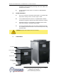
G. All air cooled units must have
all enclosure panels in place
before operating compressor.
Air will not be drawn through
the condenser coil if the
panels are not in place.
Starting the unit without the enclosure panels in place will result in a
refrigerant fault.
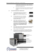
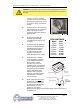
Figure 2.4B
Typical blower assembly
CFM RATINGS
Model
5 Tons
7.5 Tons
10 Tons
15 Tons
20 Tons
25 Tons
30 Tons
CFM
5,000
7,500
10,000
15,000
20,000
25,000
30,000
Figure 2.4C
WARNING: Do not attempt to duct exhaust air from a portable chiller using motor
driven fans. Exhaust air can only be ducted from a portable chiller using a blower
assembly.
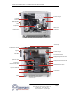
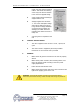
Damper assembly
Punch hole
in top panel
1/4" Copper line
Optional
Liquid receiver
(located inside
chiller on base)
Angle valve and cap
1/4" copper line connection
Figure 2.4D