
Instruction manual


Maximum Series Portable Chiller : Air & Water-Cooled : M1 Series Instrument
Page: 20
ADVANTAGE ENGINEERING, INC.
525 East Stop 18 Road Greenwood, Indiana 46142
317-887-0729 Fax: 317-881-1277
Service Department Fax: 317-885-8683
Email: service@AdvantageEngineering.com
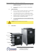
power entry hole into the electrical
cabinet. This allows the matching
of the entry hole size and location
tothecustomersuppliedttings.
5. Aunitspecicelectricaldrawingis
shipped with the unit.
6. Voltage supplies must be within
+/- 10% of the name plate voltage
and must be within 2% from leg
to leg. Extreme voltage imbalance
or using the wrong voltage can
damage your chiller and cause
premature unit failure as well as a
safety risk.
7. A proper ground is required for the
unit.
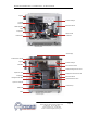
B. CONTROL CIRCUIT WIRING
1. Theunit’ssuppliedcontrolcircuitis110volt,1phase,60
cycle.
2. The control circuit is supplied by the factory installed
transformer. A control circuit fuse is provided.
C. GENERAL
1. Make certain all ground connections to the unit are properly
afxed.
2. Make certain power conductor, disconnecting means, and
fusingareproperlysizedaccordingtotheunit’spower
supply requirements.
3. Follow all local and national codes.
4. Make certain that all owner and factory wire connections are
tight before applying power to the unit.
WARNING: Check that all electrical connections are tight before starting.
Disconnect power before servicing. Follow all facility lock-out tag-out procedures.
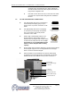
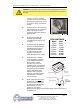
Typical data tag.