
Instruction manual


Maximum Series Portable Chiller : Air & Water-Cooled : M1 Series Instrument
Page: 25
ADVANTAGE ENGINEERING, INC.
525 East Stop 18 Road Greenwood, Indiana 46142
317-887-0729 Fax: 317-881-1277
Service Department Fax: 317-885-8683
Email: service@AdvantageEngineering.com
See Section 6.3.J for more information.
Please note, Sections 3.2.A & 5.4 are not applicable for
reverseowunits.
3. WATER QUALITY CONTROL. Lack of, as well as, improper
water treatment can damage the chilling unit. The services
of competent water treatment specialist should be obtained
and their recommendations followed. It is the equipment
owner’sresponsibilitytopreventdamagefromforeign
material or inadequate water treatment. See water treatment
section in section 1.6 of this manual for more information.
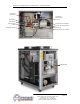
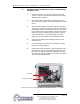
4. FOR AUTOMATIC FILL: Always install a manual shut off
valve on the make-up water supply on the outside of the
unit. When electrical power
is applied to the unit but the
On/Off Selector is in the
‘off’positionopentheowner
supplied shut off valve. The
level switch will activate the
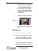
make-upsolenoid(gure
3.2A), which will open and
thewatersupplywillll
the reservoir tank. Do not
use automatic ll when
operating at temperature
below 48°F.
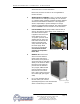
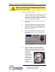
5. MANUAL FILL: Disconnect
and lock out the electrical
power supply and remove
all necessary cover panels to
accessthereservoir.Adduid
directly to the reservoir. When
thepumpisrststarted,as
processlinesarelledand
airispurged,additionaluid
may be required to restore
the reservoir to the correct
level. Verify reservoir level via
thecoolantsightglass(gure
3.2B).
6. Do not use deionized water in
this unit unless your unit was
specicallydesignedforusewithdeionized
water. Consult factory if not certain.
Figure 3.2AMake-up solenoid valve
Figure 3.2B
Typical reservoir sight glass