
Instruction manual


Maximum Series Portable Chiller : Air & Water-Cooled : M1 Series Instrument
Page: 29
ADVANTAGE ENGINEERING, INC.
525 East Stop 18 Road Greenwood, Indiana 46142
317-887-0729 Fax: 317-881-1277
Service Department Fax: 317-885-8683
Email: service@AdvantageEngineering.com
maintenance. Since the evaporator in most liquid
chillersisowsensitive,theefciencyofoperation
isdirectlyrelatedtotheowofliquid.
b. Maximumchillerefciencyisobtainedat
approximately 2.4 gpm per ton of rated capacity.
Lowliquidowcanreduceefciencyandinsome
cases allow ice to develop in the evaporator which
candamagetheevaporator.Excessiveliquidow
will trip the motor overload protection circuit.
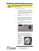
2. Switch on the illuminated ON/OFF SWITCH to activate the
process pump. Wait a few moments to allow air to be purge
from system. Observe the COOLANT pressure gauge for
steadyreadout.Checkunitforlowandhighow..
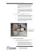
3. LOW FLOW: Ifalowowconditionispresent,besureall
process valves are open. If all process valves are open and
alowowconditionsexists,considerthefollowing:
a. Lowowcancausethelowrefrigerantpressure
limit switch to trip.
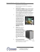
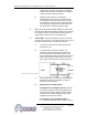
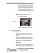
b. Tooperateunderalowowcondition,itis
necessarytoinstallaowbypasssysteminthe
process circuitry. This will allow a portion of the
owtobypasstheprocessandreturndirectlytothe
chiller.Thiskeepsthetotalowabovethecutoff
point. Figure 3.2E illustrates a typical bypass loop.
c. Some models may have a factory installed bypass.
Follow the instruction in paragraph “d” below to
adjustthelowowbypass.
d. Adjusting the Low Flow Bypass:
For Manual Low Flow Bypass Valves: Start with
the bypass completely closed and gradually open
the valve until the low refrigerant pressure gauge
reading is in the normal operating range for the
refrigerant type used in the chiller.
For Automatic Low Flow Bypass Valves:
A “T” handle or adjusting stem is located on the top
Figure3.2ETypicallowowby-passloop