
Instruction manual


Maximum Series Portable Chiller : Air & Water-Cooled : M1 Series Instrument
Page: 30
ADVANTAGE ENGINEERING, INC.
525 East Stop 18 Road Greenwood, Indiana 46142
317-887-0729 Fax: 317-881-1277
Service Department Fax: 317-885-8683
Email: service@AdvantageEngineering.com
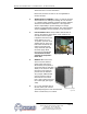
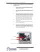
of the valve. Turning the “T” handle or adjusting
stem in the clockwise direction puts more pressure
onthevalve’sspringreducingbypassow.Turning
the “T” handle or adjusting stem counter clockwise
puts less pressure on the spring and increases
bypassow.Adjustthe“T”handleoradjusting
stem until the low pressure gauge reading is in the
normal operating range for the refrigerant type used
in the chiller. If the low pressure gauge reading is
below normal, reduce the pressure on the spring to
provide more bypass.
4. HIGH FLOW: Ifahighowconditionispresent:
a. Highowcancauseprematurecomponentwear
and poor operating conditions.
b. Adjusttheowsothatan8°F-10°Friseinwater
temperature is indicated while the system is fully
loaded.
3.3 INSTRUMENT / OPERATION
A. INSTRUMENT START-UP
1. When the correct electrical power and adequate water
supply pressure are supplied to the unit, it is possible to
start the unit.
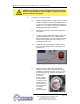
2. Upon power up, the instrument displays “ChF” indicating
that the unit is in Fahrenheit temperature mode or “ChC”
indicating that it is in Celsius mode. The control then shows
the current setpoint for approximately 2 seconds before
reverting to the To Process temperature. When power is
supplied to the unit, the ON/OFF switch will illuminate.
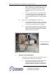
3. PRECAUTIONS:
The chiller control is programmed from the factory with a
setpoint range of 48° to 70°F. To operate below 48°F, the
additionofinhibitedpropyleneglycolandmodicationofthe
limit control settings are required. Diligent monitoring of the
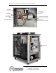
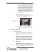
Automatic Low Flow
Bypass Valve