
Instruction manual


Maximum Series Portable Chiller : Air & Water-Cooled : M1 Series Instrument
Page: 51
ADVANTAGE ENGINEERING, INC.
525 East Stop 18 Road Greenwood, Indiana 46142
317-887-0729 Fax: 317-881-1277
Service Department Fax: 317-885-8683
Email: service@AdvantageEngineering.com
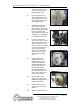
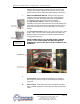
The power cord should be
removed from the motor
housing(gure5.5C).
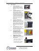
6. Locate and remove the
pump casing bolts. These
bolts secure the motor and
motor adapter to the pump
casing(gure5.5D).
7. Separate the motor and
motor adapter from the
pump casing to expose the
pumpimpeller(gure5.5E).
Remove the motor and
motor adapter from the unit
and place on a workbench
to continue the procedure.
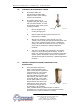
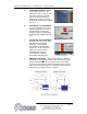
8. Locate and remove the
dust cap from motor end to
expose slotted motor shaft.
The motor shaft is free to
rotate, but must be secured
to remove the impeller. To
secure the motor shaft,
insertaatbladedscrew
driver in slot to hold the
shaft stationary (Figure
5.5F).
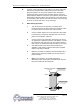
9. Locate and remove
impeller locking screw
(Figure 5.5G). Using a
socket and ratchet, the
impeller retaining screw
can be removed. Once
the retaining screw is
removed, the impeller can
be “unthreaded” from the
motor shaft to expose the
pump seal assembly.
10. Remove all seal parts
(Figure 5.5H). Note seal
component arrangement to
facilitate reassembly.
11. Clean motor shaft and
lubricate with a mild soap
solution.
12. Install new stationary seal
Typical pump casing bolt
Figure 5.5D
Motor shaft
Figure 5.5F
Typical impeller
Figure 5.5G
Impeller
Figure 5.5E