
Instruction manual


Maximum Series Portable Chiller : Air & Water-Cooled : M1 Series Instrument
Page: 56
ADVANTAGE ENGINEERING, INC.
525 East Stop 18 Road Greenwood, Indiana 46142
317-887-0729 Fax: 317-881-1277
Service Department Fax: 317-885-8683
Email: service@AdvantageEngineering.com
6.1 WATER SYSTEM
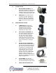
A. MOTOR/PUMP ASSEMBLY: The
motor/pump assembly circulates chilled
uidtotheprocessloop.Thepump
assembly is built of total stainless steel
tomaintainwaterquality(gure6.1A).
B. RESERVOIR. The vented reservoir
is sized for the chiller application to
supporttheowrate.Thereservoir
provides a stable water temperature
undervaryingloadconditions(gure
6.1B).
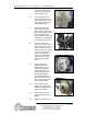
6.2 REFRIGERATION SYSTEM
A. COMPRESSOR: Compressors
take low pressure/low temperature
refrigerant gas and compress
the gas into high pressure/high
temperaturegas(gure6.2A).
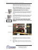
B. AIR COOLED CONDENSER: The
air cooled condenser removes heat
from the compressed refrigerant
gas. The action causes the gas to
“condense” into a liquid state still
underhighpressure.Airowacross
the condenser is achieved via a motor
driven fan assembly or centrifugal
blower.
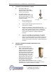
C. WATER COOLED CONDENSER:
The water cooled condenser removes
heat from the compressed refrigerant
gas. As the heat is removed, the gas
“condenses” into a liquid state, still
under high pressure. Tube-in-shell
condensers are used on 15-30 ton
models. Tube-in-tube condensers
are used on 5-10 ton models. Water
regulator valves are used on all
models to control the refrigerant head
pressure by modulating the condenser
waterow(gure6.2C).
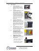
D. FILTER-DRIER: Thelter-drier
removes contaminants and moisture
fromtheliquidrefrigerant(gure6.2D).
E. LIQUID LINE SOLENOID VALVE:
TypicallterdrierFigure6.2D
Typical air-cooled condenser
Figure 6.2B
Figure 6.1B
Figure 6.2A
Figure 6.1A
Typical water-cooled
condenser Figure 6.2C